Toyota Venza: System Diagram
SYSTEM DIAGRAM
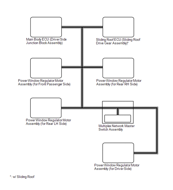
1. DOOR BUS LINES
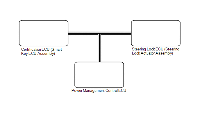
2. CERTIFICATION BUS LINES [w/ Smart Key System]
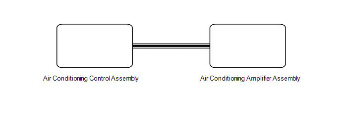
3. AIR CONDITIONING BUS LINES
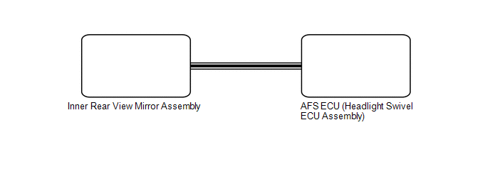
4. LIGHTING BUS LINES [w/ Smart Beam]
 System Description
SYSTEM DESCRIPTION
1. LIN COMMUNICATION SYSTEM DESCRIPTION
The LIN communication system is used for communication between the components
in the table below. If communication cannot be performed th ...
 How To Proceed With Troubleshooting
CAUTION / NOTICE / HINT
HINT:
Use the following procedure to troubleshoot the LIN communication system.
*: Use the Techstream.
PROCEDURE
1.
VEHICLE BROU ...
Other materials about Toyota Venza:
Alarm
The system sounds the alarm and flashes lights when forcible entry is detected.
- Triggering of the alarm
The alarm is triggered in the following situations when the alarm is set.
• A locked door is unlocked or opened in any way other than by using ...
Rear Wheel House Plate
Components
COMPONENTS
ILLUSTRATION
Installation
INSTALLATION
PROCEDURE
1. INSTALL NO. 2 ROCKER PANEL MOULDING PROTECTOR
(a) Install the No. 2 rocker panel moulding protector with the 2 screws
<B>.
...
Diagnosis System
DIAGNOSIS SYSTEM
1. DESCRIPTION
(a) Sliding roof system data and Diagnostic Trouble Codes (DTCs) can be read
through the vehicle Data Link Connector 3 (DLC3). When the system seems to be malfunctioning,
use the Techstream to check for malfunctions and pe ...

0.1453