Toyota Venza: Stop Light Switch
Components
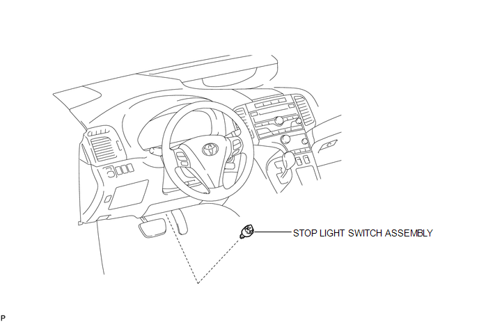
COMPONENTS
ILLUSTRATION
Removal
REMOVAL
PROCEDURE
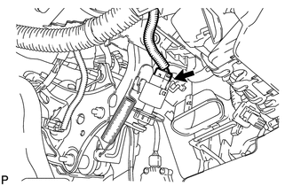
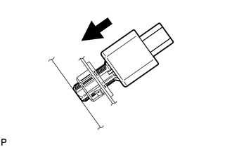
1. REMOVE STOP LIGHT SWITCH ASSEMBLY
|
(a) Disconnect the connector. |
|
|
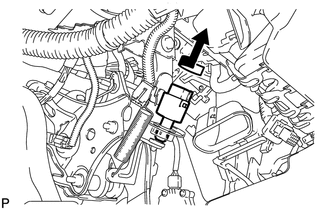
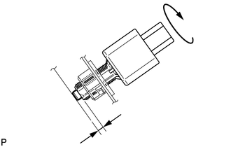
(b) Turn the stop light switch assembly counterclockwise and remove the stop light switch assembly. |
|
Inspection
INSPECTION
PROCEDURE
1. INSPECT STOP LIGHT SWITCH ASSEMBLY
(a) Measure the resistance according to the value(s) in the table below.
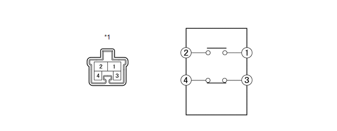
Standard Resistance:
|
Tester Connection |
Switch Condition |
Specified Condition |
|---|---|---|
|
1 - 2 |
Pushed |
10 kΩ or higher |
|
Not pushed |
Below 1 Ω |
|
|
3 - 4 |
Pushed |
Below 1 Ω |
|
Not pushed |
10 kΩ or higher |
|
*1 |
Component without harness connected (Stop Light Switch Assembly) |
If the result is not as specified, replace the stop light switch assembly.
Installation
INSTALLATION
PROCEDURE
1. INSTALL STOP LIGHT SWITCH ASSEMBLY
|
(a) Insert the stop light switch assembly until the rod hits the pedal. NOTICE: When inserting the stop light switch assembly, support the pedal from behind so that the pedal is not depressed. |
|
|
(b) Make a quarter turn clockwise to install the stop light switch assembly. Torque: 1.5 N·m {15 kgf·cm, 13 in·lbf} or less NOTICE: When inserting the stop light switch assembly, support the pedal from behind so that the pedal is not depressed. |
|
(c) Connect the connector.
(d) Check the protrusion of the rod.
Protrusion of the rod:
1.5 to 2.5 mm (0.0591 to 0.0984 in.)
If the protrusion is not as specified, adjust it.
NOTICE:
Do not depress the brake pedal.
 Side Turn Signal Light Assembly
Components
COMPONENTS
ILLUSTRATION
Removal
REMOVAL
CAUTION / NOTICE / HINT
HINT:
Use the same procedure for the RH and LH sides.
The procedure described below is for the LH si ...
 Turn Signal Flasher Assembly
Components
COMPONENTS
ILLUSTRATION
Inspection
INSPECTION
PROCEDURE
1. INSPECT TURN SIGNAL FLASHER ASSEMBLY
(a) Disconnect the D34 turn signal flasher assembly connector.
...
Other materials about Toyota Venza:
Air Conditioning Control Panel Circuit
DESCRIPTION
This circuit consists of the air conditioning control assembly and the A/C amplifier.
When the air conditioning control assembly is operated, signals are transmitted
to the A/C amplifier through the LIN communication system.
If the LIN commun ...
Washer Motor(for Rear Side)
Components
COMPONENTS
ILLUSTRATION
Removal
REMOVAL
PROCEDURE
1. REMOVE FRONT WHEEL RH
2. REMOVE FRONT FENDER OUTSIDE MOULDING RH
HINT:
Use the same procedure for the RH side and LH side (See page
).
3. REMOVE FRONT FENDER LINER RH
4. DRAI ...
Diagnostic Trouble Code Chart
DIAGNOSTIC TROUBLE CODE CHART
HINT:
If a trouble code is output during the DTC check, inspect the trouble areas listed
for that code. For details of the code, refer to "See page" in the DTC chart.
Inspect the fuses and relays before troub ...

0.1629