Toyota Venza: Side Turn Signal Light Assembly
Components
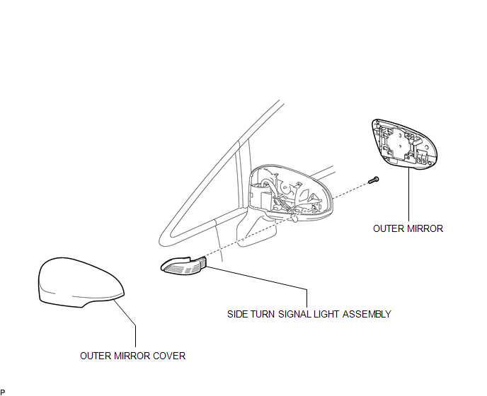
COMPONENTS
ILLUSTRATION
Removal
REMOVAL
CAUTION / NOTICE / HINT
HINT:
- Use the same procedure for the RH and LH sides.
- The procedure described below is for the LH side.
PROCEDURE
1. REMOVE OUTER MIRROR
.gif)
2. REMOVE OUTER MIRROR COVER
3. REMOVE SIDE TURN SIGNAL LIGHT ASSEMBLY
|
(a) Remove the screw. |
|
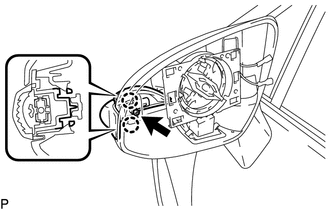
(b) Disengage the 2 claws.
(c) Disconnect the connector and remove the side turn signal light assembly.
Inspection
INSPECTION
PROCEDURE
1. INSPECT SIDE TURN SIGNAL LIGHT ASSEMBLY LH
|
(a) Connect a positive (+) lead from the battery to terminal 1 and a negative (-) lead to terminal 2. |
|
.png)
(b) Check that the side turn signal light comes on.
OK:
The light comes on.
Text in Illustration|
*1 |
Component without harness connected (Side Turn Signal Light Assembly LH) |
If the result is not as specified, replace the side turn signal light assembly LH.
2. INSPECT SIDE TURN SIGNAL LIGHT ASSEMBLY RH
|
(a) Connect a positive (+) lead from the battery to terminal 1 and a negative (-) lead to terminal 2. |
|
(b) Check that the side turn signal light comes on.
OK:
The light comes on.
Text in Illustration|
*1 |
Component without harness connected (Side Turn Signal Light Assembly RH) |
If the result is not as specified, replace the side turn signal light assembly RH.
Installation
INSTALLATION
CAUTION / NOTICE / HINT
HINT:
- Use the same procedure for the RH and LH sides.
- The procedure described below is for the LH side.
PROCEDURE
1. INSTALL SIDE TURN SIGNAL LIGHT ASSEMBLY
(a) Connect the connector.
(b) Engage the 2 claws.
(c) Install the side turn signal light assembly with the screw.
2. INSTALL OUTER MIRROR COVER
.gif)
3. INSTALL OUTER MIRROR
 Relay
Relay
On-vehicle Inspection
ON-VEHICLE INSPECTION
PROCEDURE
1. INSPECT TAILLIGHT RELAY (TAIL)
(a) Remove the taillight relay from the main body ECU (driver side junction
block assembly) ...
 Stop Light Switch
Components
COMPONENTS
ILLUSTRATION
Removal
REMOVAL
PROCEDURE
1. REMOVE STOP LIGHT SWITCH ASSEMBLY
(a) Disconnect the connector.
...
Other materials about Toyota Venza:
Data List / Active Test
DATA LIST / ACTIVE TEST
1. DATA LIST
HINT:
Using the Techstream to read the Data List allows the values or states of switches,
sensors, actuators and other items to be read without removing any parts. This non-intrusive
inspection can be very useful bec ...
A/C ECU Vehicle Information Reading/Writing Processor Malfunction (B15F5)
DESCRIPTION
This DTC is stored when items controlled by the air conditioning amplifier assembly
cannot be customized via the navigation system vehicle customization screen.
HINT:
The air conditioning amplifier assembly controls the air conditioning system ...
Monitor Drive Pattern
MONITOR DRIVE PATTERN
1. TEST MONITOR DRIVE PATTERN FOR ECT
CAUTION:
Perform this drive pattern on a level surface and strictly observe the posted
speed limits and traffic laws while driving.
HINT:
Performing this drive pattern is one method to simulate ...

0.1537