Toyota Venza: Turn Signal Flasher Assembly
Components
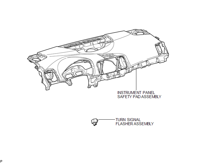
COMPONENTS
ILLUSTRATION
Inspection
INSPECTION
PROCEDURE
1. INSPECT TURN SIGNAL FLASHER ASSEMBLY
|
(a) Disconnect the D34 turn signal flasher assembly connector. |
|
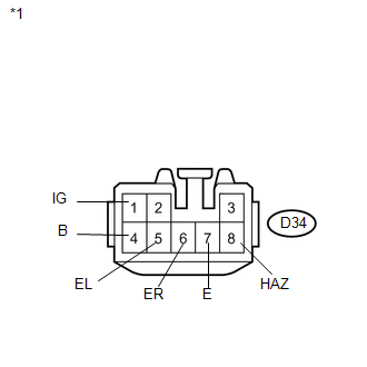
(b) Measure the voltage according to the value(s) in the table below.
Standard Voltage:
|
Tester Connection |
Condition |
Specified Condition |
|---|---|---|
|
D34-1 (IG) - Body ground |
Ignition switch off |
Below 1 V |
|
Ignition switch ON |
11 to 14 V |
|
|
D34-4 (B) - Body ground |
Always |
11 to 14 V |
|
*1 |
Front view of wire harness connector (to Turn Signal Flasher Assembly) |
If the result is not as specified, repair or replace the wire harness or connector.
(c) Measure the resistance according to the value(s) in the table below.
Standard Resistance:
|
Tester Connection |
Condition |
Specified Condition |
|---|---|---|
|
D34-5 (EL) - Body ground |
Turn signal switch off |
10 kΩ or higher |
|
Turn signal switch in left turn position |
Below 1 Ω |
|
|
D34-6 (ER) - Body ground |
Turn signal switch in neutral position |
10 kΩ or higher |
|
Turn signal switch in right turn position |
Below 1 Ω |
|
|
D34-7 (E) - Body ground |
Always |
Below 1 Ω |
|
D34-8 (HAZ) - Body ground |
Hazard warning switch off |
10 kΩ or higher |
|
Hazard warning switch on |
Below 1 Ω |
If the result is not as specified, repair or replace the wire harness or connector.
|
(d) Reconnect the D34 turn signal flasher assembly connector. |
|
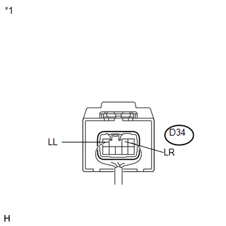
(e) Measure the voltage according to the valve(s) in the table below.
Standard Voltage:
|
Tester Connection |
Condition |
Specified Condition |
|---|---|---|
|
D34-2 (LR) - Body ground |
Hazard warning switch off |
Below 1 V |
|
Hazard warning switch on |
11 to 14 V (60 to 120 times per minute) |
|
|
Turn signal switch off |
Below 1 V |
|
|
Ignition switch ON and turn signal switch in RH position |
11 to 14 V (60 to 120 times per minute) |
|
|
D34-3 (LL) - Body ground |
Hazard warning switch off |
Below 1 V |
|
Hazard warning switch on |
11 to 14 V (60 to 120 times per minute) |
|
|
Turn signal switch off |
Below 1 V |
|
|
Ignition switch ON and turn signal switch in LH position |
11 to 14 V (60 to 120 times per minute) |
|
*1 |
Component with harness connected (Turn Signal Flasher Assembly) |
If the result is not as specified, replace the turn signal flasher assembly.
Removal
REMOVAL
PROCEDURE
1. REMOVE INSTRUMENT PANEL SAFETY PAD ASSEMBLY
HINT:
Refer to the procedure up to Remove Instrument Panel Safety Pad Assembly (See
page .gif) ).
).
2. REMOVE TURN SIGNAL FLASHER ASSEMBLY
|
(a) Disconnect the connector. |
|
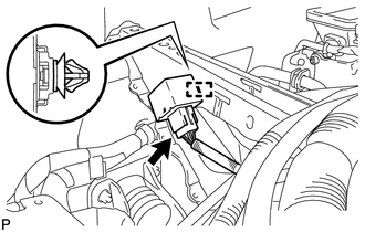
(b) Disengage the clamp and remove the turn signal flasher assembly.
Installation
INSTALLATION
PROCEDURE
1. INSTALL TURN SIGNAL FLASHER ASSEMBLY
|
(a) Engage the clamp to install the turn signal flasher assembly. |
|
.png)
(b) Connect the connector.
2. INSTALL INSTRUMENT PANEL SAFETY PAD ASSEMBLY
HINT:
Refer to the procedure from Install Instrument Panel Safety Pad Assembly (See
page .gif) ).
).
 Stop Light Switch
Components
COMPONENTS
ILLUSTRATION
Removal
REMOVAL
PROCEDURE
1. REMOVE STOP LIGHT SWITCH ASSEMBLY
(a) Disconnect the connector.
...
 Mirror (ext)
...
Other materials about Toyota Venza:
On-vehicle Inspection
ON-VEHICLE INSPECTION
PROCEDURE
1. INSPECT STEERING WHEEL FREE PLAY
(a) Stop the vehicle and position the front wheels straight ahead.
(b) Gently turn the steering wheel right and left, and check the steering wheel
free play.
Maximum free play:
30 mm ...
Catalyst System Efficiency Below Threshold (Bank 1) (P0420)
MONITOR DESCRIPTION
The ECM uses sensors mounted in front of and behind the Three-Way Catalytic Converter
(TWC) to monitor its efficiency.
The first sensor, the air fuel ratio sensor, sends pre-catalyst information to
the ECM. The second sensor, the heat ...
Diagnostic Trouble Code Chart
DIAGNOSTIC TROUBLE CODE CHART
If a trouble code is displayed during the DTC check, check the parts listed for
that code in the table below and proceed to the appropriate page.
HINT:
The steering lock ECU does not store DTCs regarding the past problems.
S ...

0.1827