Toyota Venza: Steering Position Sensor Malfunction (B2414)
DESCRIPTION
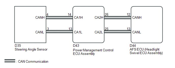
The AFS ECU (headlight swivel ECU assembly) receives signals indicating the swerve-angle from the steering angle sensor using CAN communication.
|
DTC No. |
DTC Detection Condition |
Trouble Area |
|---|---|---|
|
B2414 |
Malfunction in steering angle sensor |
|
WIRING DIAGRAM
CAUTION / NOTICE / HINT
NOTICE:
First perform the communication function inspections in How to Proceed with Troubleshooting to confirm that there are no CAN communication malfunctions before troubleshooting this symptom.
PROCEDURE
|
1. |
CHECK FOR DTC |
(a) Clear the DTCs (See page .gif) ).
).
(b) Check for DTCs (See page ).
OK:
DTC B2414 is not output.
| OK | .gif) |
USE SIMULATION METHOD TO CHECK |
|
.gif)
|
2. |
REPLACE STEERING ANGLE SENSOR |
(a) Temporarily replace the steering angle sensor with a new or normally functioning
one (See page ).
|
|
3. |
CHECK FOR DTC |
(a) Clear the DTCs (See page ).
(b) Check for DTCs (See page ).
OK:
DTC B2414 is not output.
| OK | |
END |
| NG | |
REPLACE AFS ECU (HEADLIGHT SWIVEL ECU ASSEMBLY) |
 Lost Communication with AFS LIN (B124D)
DESCRIPTION
The DTC is stored when the main body ECU (driver side junction block assembly)
detects malfunctions in the LIN communication system.
DTC No.
DTC Detection Conditi ...
 Headlight Relay Circuit
DESCRIPTION
The main body ECU (driver side junction block assembly) controls the headlight
relays.
WIRING DIAGRAM
CAUTION / NOTICE / HINT
NOTICE:
Inspect the fuses for circuits related to t ...
Other materials about Toyota Venza:
Voice is not Recognized
PROCEDURE
1.
CHECK CONDITION
(a) Check if the system voice recognition level is low when recognizing a particular
voice.
Result
Proceed to
System voice recognition level is low only fo ...
On-vehicle Inspection
ON-VEHICLE INSPECTION
PROCEDURE
1. INSPECT DISCHARGE HEADLIGHT BULB
NOTICE:
Confirm the following items before replacing a discharge headlight bulb. If a
malfunction is discovered and repaired, perform the inspection again to confirm
the repair.
...
Removal
REMOVAL
CAUTION / NOTICE / HINT
HINT:
Use the same procedure for the RH side and LH side.
The procedure listed below is for the LH side.
PROCEDURE
1. PRECAUTION
CAUTION:
Be sure to read Precaution thoroughly before servicing (See page
...

0.121