Toyota Venza: Removal
REMOVAL
CAUTION / NOTICE / HINT
HINT:
- Use the same procedure for the LH side and RH side.
- The following procedure listed is for the LH side.
PROCEDURE
1. REMOVE FRONT WHEEL
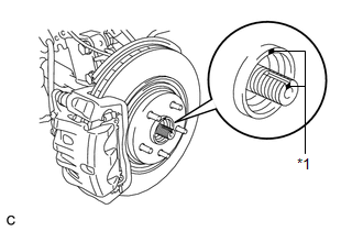
2. REMOVE FRONT AXLE SHAFT NUT
.gif)
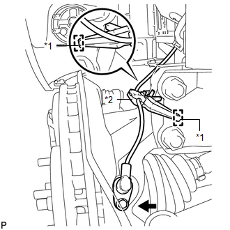
3. SEPARATE FRONT SPEED SENSOR
|
(a) Remove the bolt and resin clamp, and separate the front speed sensor. Text in Illustration
NOTICE:
|
|
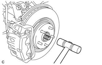
4. SEPARATE FRONT DRIVE SHAFT ASSEMBLY
|
(a) Put matchmarks on the front drive shaft assembly and front axle hub sub-assembly. Text in Illustration
|
|
|
(b) Using a plastic hammer, separate the front drive shaft assembly from the front axle assembly. NOTICE: Loosen the staked part of the front axle hub nut completely, otherwise the threads of the drive shaft may be damaged. |
|
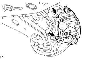
5. SEPARATE FRONT DISC BRAKE CALIPER ASSEMBLY
|
(a) Remove the 2 bolts and separate the front disc brake caliper assembly. NOTICE: Use wire or an equivalent tool to keep the brake caliper from hanging down by the flexible hose. |
|
6. REMOVE FRONT DISC
7. SEPARATE TIE ROD ASSEMBLY
8. SEPARATE FRONT LOWER SUSPENSION ARM
|
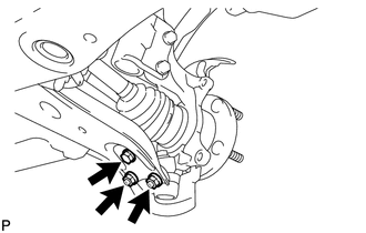
(a) Remove the bolt, 2 nuts, and separate the front lower suspension arm from the lower ball joint. |
|
9. REMOVE FRONT AXLE ASSEMBLY
|
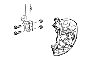
(a) Remove the 2 bolts, 2 nuts and front axle assembly. NOTICE: When removing the nuts, keep the bolts from rotating. |
|
10. REMOVE FRONT LOWER BALL JOINT
|
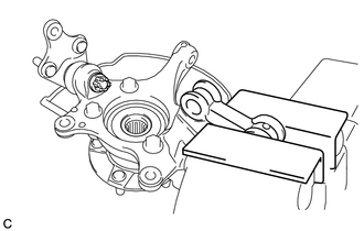
(a) Secure the front axle assembly in a vise using aluminum plates. NOTICE: When using a vise, do not overtighten it. |
|
|
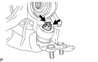
(b) Remove the cotter pin and nut. |
|
|
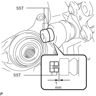
(c) Install SST to the front lower ball joint as shown in the illustration. SST: 09960-20010 09961-02050 09961-02050 NOTICE: Check that the clearance measurement between SST and the front axle assembly is 1 mm (0.0394 in.). |
|
(d) Using SST, remove the front lower ball joint from the front axle assembly as shown in the illustration.
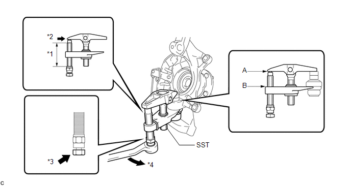 Text in Illustration
|
*1 |
Apply grease |
*3 |
Place the wrench here |
|
*2 |
Apply grease |
*4 |
Turn |
SST: 09960-20010
09961-02010
09961-02050
09961-02050
CAUTION:
Apply grease to the threads and end of the SST bolt.
NOTICE:
- Install SST so that A and B are parallel.
- Be sure to place a wrench on the part indicated in the illustration.
- Do not damage the front lower ball joint dust cover, or steering knuckle.
 Inspection
INSPECTION
PROCEDURE
1. INSPECT FRONT LOWER BALL JOINT
(a) Inspect the turning torque of the ball joint.
(1) Secure the front lower ball joint in a vise using aluminum plates.
(2) ...
 Installation
INSTALLATION
CAUTION / NOTICE / HINT
HINT:
Use the same procedure for the LH side and RH side.
The following procedure listed is for the LH side.
PROCEDURE
1. INSTALL FRONT LOWE ...
Other materials about Toyota Venza:
Radio Antenna Pole
Components
COMPONENTS
ILLUSTRATION
Removal
REMOVAL
PROCEDURE
1. REMOVE ROOF ANTENNA POLE SUB-ASSEMBLY
(a) Turn the roof antenna pole sub-assembly in the direction indicated
by the arrow in the illustration to remove it.
...
Automatic door locking and unlocking systems
The following functions can be set or canceled:
- Setting and canceling the functions
► Setting and canceling the functions
Vehicles with TFT type multi-information display The function settings can be changed
using the multi-information dis ...
Removal
REMOVAL
CAUTION / NOTICE / HINT
HINT:
The front side fix window assembly can be reused. When installing the
window, if any of the clips on the front side fix window assembly are broken,
butyl tape can be used to support the glass until the a ...

0.1142