Toyota Venza: Headlight Relay Circuit
DESCRIPTION
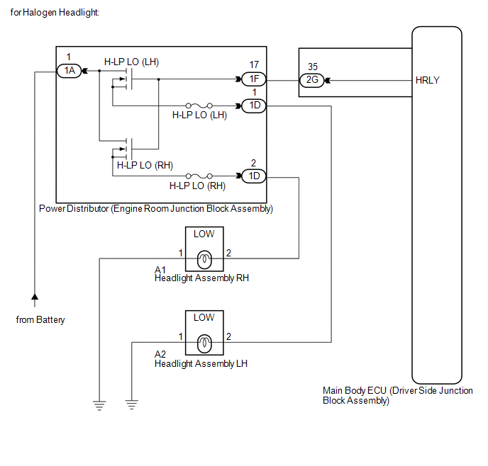
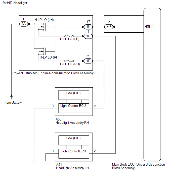
The main body ECU (driver side junction block assembly) controls the headlight relays.
WIRING DIAGRAM
CAUTION / NOTICE / HINT
NOTICE:
Inspect the fuses for circuits related to this system before performing the following inspection procedure.
PROCEDURE
|
1. |
PERFORM ACTIVE TEST USING TECHSTREAM |
(a) Connect the Techstream to the DLC3.
(b) Turn the ignition switch to ON.
(c) Turn the Techstream on.
(d) Enter the following menus: Body Electrical / Main Body / Active Test.
(e) Check that the relays operate.
Main Body|
Tester Display |
Test Part |
Control Range |
Diagnostic Note |
|---|---|---|---|
|
Headlight Relay |
Headlight Relay |
ON/OFF |
- |
OK:
Headlight relays operate. (Low beam headlights illuminate.)
| OK | .gif) |
PROCEED TO NEXT SUSPECTED AREA SHOWN IN PROBLEM SYMPTOMS TABLE |
|
.gif)
|
2. |
INSPECT ENGINE ROOM JUNCTION BLOCK ASSEMBLY |
|
(a) Remove the power distributor (engine room junction block assembly)
from the engine room relay block (See page
|
|
.gif) ).
).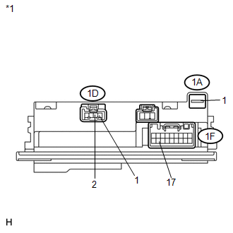
(b) Connect a positive (+) lead from the battery to terminal 1A-1.
(c) Connect a negative (-) lead from the battery to terminal 1F-17.
(d) Measure the voltage according to the value(s) in the table below.
Standard Voltage:
|
Tester Connection |
Condition |
Specified Condition |
|---|---|---|
|
1D-1 - Battery negative |
Always |
11 to 14 V |
|
1D-2 - Battery negative |
Always |
11 to 14 V |
|
*1 |
Component without harness connected (Power Distributor (Engine Room Junction Block Assembly)) |
| NG | |
REPLACE POWER DISTRIBUTOR (ENGINE ROOM JUNCTION BLOCK ASSEMBLY) |
|
|
3. |
CHECK HARNESS AND CONNECTOR (BATTERY - ENGINE ROOM JUNCTION BLOCK ASSEMBLY) |
|
(a) Disconnect the 1A power distributor (engine room junction block assembly) connector. |
|
(b) Measure the voltage according to the value(s) in the table below.
Standard Voltage:
|
Tester Connector |
Condition |
Specified Condition |
|---|---|---|
|
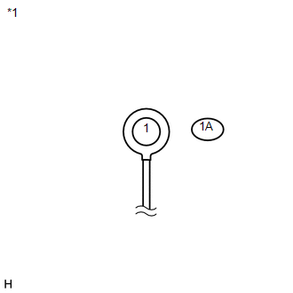
1A-1 - Body ground |
Always |
11 to 14 V |
|
*1 |
Front view of wire harness connector (to Power Distributor (Engine Room Junction Block Assembly)) |
| NG | |
REPAIR OR REPLACE HARNESS OR CONNECTOR |
|
|
4. |
CHECK HARNESS AND CONNECTOR (ENGINE ROOM JUNCTION BLOCK ASSEMBLY - MAIN BODY ECU) |
|
(a) Disconnect the 1F power distributor (engine room junction block assembly) connector. |
|
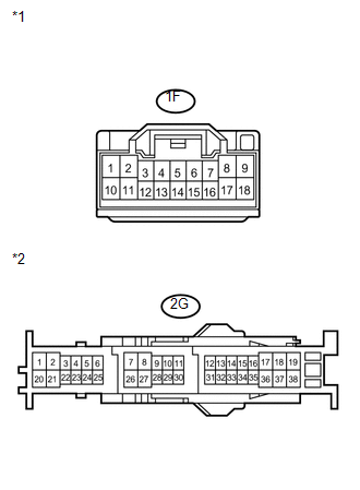
(b) Disconnect the 2G main body ECU (driver side junction block assembly) connector.
(c) Measure the resistance according to the value(s) in the table below.
Standard Resistance:
|
Tester Connection |
Condition |
Specified Condition |
|---|---|---|
|
1F-17 - 2G-35 |
Always |
Below 1 Ω |
|
1F-17 - Body ground |
Always |
10 kΩ or higher |
|
*1 |
Front view of wire harness connector (to Power Distributor (Engine Room Junction Block Assembly)) |
|
*2 |
Front view of wire harness connector (to Main Body ECU (Driver Side Junction Block Assembly)) |
| OK | |
REPLACE MAIN BODY ECU (DRIVER SIDE JUNCTION BLOCK ASSEMBLY) |
| NG | |
PROCEED TO NEXT SUSPECTED AREA SHOWN IN PROBLEM SYMPTOMS TABLE |
 Steering Position Sensor Malfunction (B2414)
DESCRIPTION
The AFS ECU (headlight swivel ECU assembly) receives signals indicating the swerve-angle
from the steering angle sensor using CAN communication.
DTC No.
DTC Detec ...
 Headlight Solenoid Circuit
DESCRIPTION
for HID Headlight:
When the main body ECU receives a high beam turn on signal, the main
body ECU activates the bi-function by controlling the BI-XENON relay. The
bi-func ...
Other materials about Toyota Venza:
Removal
REMOVAL
PROCEDURE
1. DISCHARGE FUEL SYSTEM PRESSURE
HINT:
(See page ).
2. DISCONNECT CABLE FROM NEGATIVE BATTERY TERMINAL
NOTICE:
When disconnecting the cable, some systems need to be initialized after the cable
is reconnected (See page ).
3. REMOV ...
Diagnosis System
DIAGNOSIS SYSTEM
1. DESCRIPTION
(a) The power back door ECU (power back door motor unit) controls the power back
door system functions. Power back door system data and Diagnostic Trouble Code (DTC)
can be read through the Data Link Connector 3 (DLC3).
W ...
Microphone Circuit between Microphone and Radio Receiver
DESCRIPTION
The radio and display receiver assembly and inner rear view mirror assembly (amplifier
microphone assembly) are connected to each other using the microphone connection
detection signal lines.
Using this circuit, the radio and display receiver ...

0.1263