Toyota Venza: Reassembly
REASSEMBLY
PROCEDURE
1. INSTALL NO. 3 ANTENNA CORD SUB-ASSEMBLY
.gif)
2. INSTALL ROOF HEADLINING ASSEMBLY
HINT:
Refer to the procedure from Install Roof Headlining Assembly (See page
).
3. INSTALL REAR WIPER MOTOR AND BRACKET ASSEMBLY
4. INSTALL REAR WIPER MOTOR GROMMET
5. INSTALL REAR WIPER ARM AND BLADE ASSEMBLY
6. INSTALL REAR WIPER ARM HEAD CAP
7. INSTALL REAR WASHER NOZZLE
8. INSPECT REAR WASHER NOZZLE
9. ADJUST REAR WASHER NOZZLE
10. INSTALL REAR SPOILER ASSEMBLY
11. INSTALL LICENSE PLATE LIGHT ASSEMBLY
12. INSTALL BACK DOOR OUTSIDE GARNISH SUB-ASSEMBLY
13. INSTALL REAR LIGHT ASSEMBLY LH
14. INSTALL REAR LIGHT ASSEMBLY RH
HINT:
Use the same procedure for the RH side and LH side.
15. INSTALL AMPLIFIER ANTENNA ASSEMBLY
16. INSTALL POWER BACK DOOR WARNING BUZZER (w/ Power Back Door)
17. INSTALL BACK DOOR LOWER DAMPER STAY BRACKET LH
18. INSTALL BACK DOOR LOWER DAMPER STAY BRACKET RH
HINT:
Use the same procedure for the RH side and LH side.
19. INSTALL BACK DOOR STAY ASSEMBLY LH
20. INSTALL BACK DOOR STAY ASSEMBLY RH
HINT:
Use the same procedure for the RH side and LH side.
21. INSTALL POWER BACK DOOR TOUCH SENSOR ASSEMBLY LH (w/ Power Back Door)
22. INSTALL POWER BACK DOOR TOUCH SENSOR ASSEMBLY RH (w/ Power Back Door)
HINT:
Use the same procedure for the RH side and LH side.
23. INSTALL BACK DOOR LOCK ASSEMBLY
(a) Apply MP grease to the sliding parts of the back door lock assembly.
(b) Apply adhesive to the threads of the bolt.
Adhesive:
Toyota Genuine Adhesive 1324, Three Bond 1324 or equivalent
|
(c) Install the back door lock assembly with the 3 bolts. Torque: 8.0 N·m {82 kgf·cm, 71 in·lbf} |
|
.png)
|
(d) Install the bolt. Torque: 8.0 N·m {82 kgf·cm, 71 in·lbf} |
|
.png)
(e) Engage the clamp.
(f) Connect the connector.
24. INSTALL POWER BACK DOOR CLOSER SWITCH ASSEMBLY (w/ Power Back Door)
25. INSTALL DOOR PULL HANDLE
|
(a) Engage the 4 claws to install the back door pull handle. |
|
26. INSTALL BACK DOOR TRIM COVER RH
|
(a) Engage the 2 clips to install the back door trim cover RH. |
|
.png)
27. INSTALL UPPER BACK DOOR STAY BRACKET LH
|
(a) Install the upper back door stay bracket LH with the 2 bolts. Torque: 13 N·m {133 kgf·cm, 10 ft·lbf} |
|
.png)
28. INSTALL BACK DOOR TRIM COVER LH (w/o Power Back Door)
|
(a) Engage the 2 clips to install the back door trim cover LH. |
|
.png)
29. INSTALL BACK DOOR TRIM COVER LH (w/ Power Back Door)
|
(a) Engage the 2 clips to install the back door trim cover LH. |
|
.png)
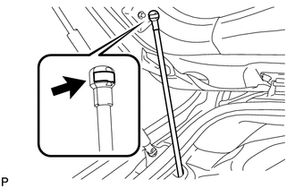
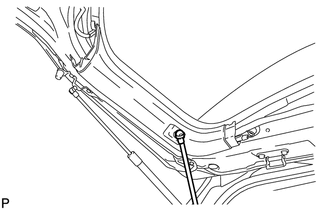
30. CONNECT POWER BACK DOOR ROD (w/ Power Back Door)
|
(a) Install the stop ring to the power back door rod. |
|
|
(b) Install the power back door rod. |
|
31. INSTALL BACK DOOR PANEL TRIM ASSEMBLY
|
(a) Engage the 16 clips and install the back door panel trim assembly. |
|
.png)
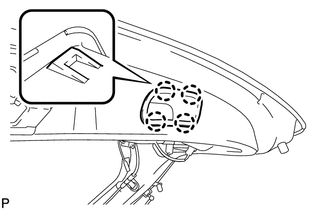
32. INSTALL UPPER BACK WINDOW PANEL TRIM
|
(a) Engage the 4 clips and 4 claws to install the upper back window panel trim. |
|
.png)
 Disassembly
DISASSEMBLY
PROCEDURE
1. REMOVE UPPER BACK WINDOW PANEL TRIM
(a) Disengage the 4 clips and 4 claws, and remove the upper back window
panel trim.
...

Other materials about Toyota Venza:
Intake Air Temperature Sensor Gradient Too High (P0111)
DESCRIPTION
The intake air temperature sensor, mounted on the mass air flow meter,
monitors the intake air temperature. The intake air temperature sensor has
a built-in thermistor with a resistance that varies according to the temperature
...
Check Mode Procedure
CHECK MODE PROCEDURE
HINT:
Techstream only:
Compared to normal mode, check mode is more sensitive to malfunctions. Therefore,
check mode can detect malfunctions that cannot be detected in normal mode.
NOTICE:
All the stored DTCs and freeze frame data ar ...
Door Control Transmitter(w/ Smart Key System)
Components
COMPONENTS
ILLUSTRATION
Removal
REMOVAL
PROCEDURE
1. REMOVE TRANSMITTER BATTERY
Inspection
INSPECTION
PROCEDURE
1. INSPECT DOOR CONTROL TRANSMITTER
(a) Inspect operation of the transmitter.
(1) Remove the battery (lithium batt ...

0.1717