Toyota Venza: Navigation Antenna
Components
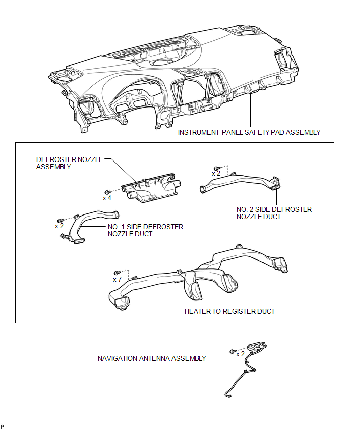
COMPONENTS
ILLUSTRATION
Removal
REMOVAL
PROCEDURE
1. REMOVE INSTRUMENT PANEL SAFETY PAD ASSEMBLY
HINT:
Refer to the procedure up to Remove Instrument Panel Safety Pad Assembly (See
page .gif) ).
).
2. REMOVE NO. 1 SIDE DEFROSTER NOZZLE DUCT
3. REMOVE NO. 2 SIDE DEFROSTER NOZZLE DUCT
4. REMOVE DEFROSTER NOZZLE ASSEMBLY
5. REMOVE HEATER TO REGISTER DUCT
6. REMOVE NAVIGATION ANTENNA ASSEMBLY
|
(a) Disengage the 4 clamps. |
|
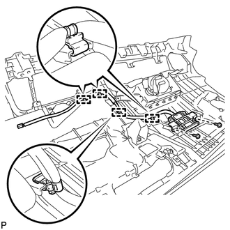
(b) Remove the 2 screws and the navigation antenna assembly.
Installation
INSTALLATION
PROCEDURE
1. INSTALL NAVIGATION ANTENNA ASSEMBLY
|
(a) Install the navigation antenna assembly with the 2 screws. |
|
.png)
(b) Engage the 4 clamps.
2. INSTALL HEATER TO REGISTER DUCT
.gif)
3. INSTALL DEFROSTER NOZZLE ASSEMBLY
4. INSTALL NO. 2 SIDE DEFROSTER NOZZLE DUCT
5. INSTALL NO. 1 SIDE DEFROSTER NOZZLE DUCT
6. INSTALL INSTRUMENT PANEL SAFETY PAD ASSEMBLY
HINT:
Refer to the procedure from Install Roof Headlining Assembly (See page
).


Other materials about Toyota Venza:
Removal
REMOVAL
CAUTION / NOTICE / HINT
HINT:
Use the same procedure for the RH side and LH side.
The procedure listed below is for the LH side.
PROCEDURE
1. REMOVE REAR WHEEL
2. REMOVE DECK SIDE TRIM
(a) Disengage the 5 claws, and ...
Ignition Key Cylinder Light
Components
COMPONENTS
ILLUSTRATION
Inspection
INSPECTION
PROCEDURE
1. INSPECT TRANSPONDER KEY AMPLIFIER
(a) Connect a positive (+) lead from battery to terminal 2 and a negative
(-) lead to terminal 6.
...
Components
COMPONENTS
ILLUSTRATION
ILLUSTRATION
ILLUSTRATION
ILLUSTRATION
ILLUSTRATION
...

0.1366