Toyota Venza: High Mounted Stop Light Assembly
Components
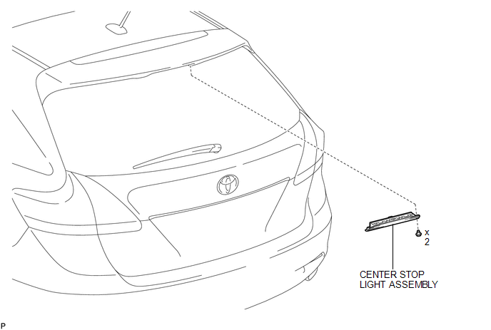
COMPONENTS
ILLUSTRATION
Removal
REMOVAL
PROCEDURE
1. REMOVE CENTER STOP LIGHT ASSEMBLY
|
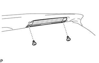
(a) Using a short screwdriver, remove the 2 screws. |
|
(b) Disconnect the connector and remove the center stop light assembly.
Inspection
INSPECTION
PROCEDURE
1. INSPECT CENTER STOP LIGHT ASSEMBLY
|
(a) Connect a positive (+) lead from the battery to terminal 2 and a negative (-) lead to terminal 1. |
|
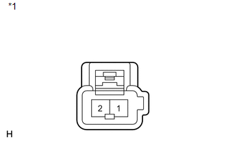
(b) Check that the light comes on.
OK:
The light comes on.
Text in Illustration|
*1 |
Component without harness connected (Center Stop Light Assembly) |
If the result is not as specified, replace the center stop light assembly.
Installation
INSTALLATION
PROCEDURE
1. INSTALL CENTER STOP LIGHT ASSEMBLY
(a) Connect the connector.
|
(b) Using a short screwdriver, install the center stop light assembly with the 2 screws. |
|
.png)
 Removal
REMOVAL
CAUTION / NOTICE / HINT
PROCEDURE
1. PRECAUTION
NOTICE:
After turning the ignition switch off, waiting time may be required before disconnecting
the cable from the negative (-) battery ...
 License Plate Light Assembly
Components
COMPONENTS
ILLUSTRATION
ILLUSTRATION
Installation
INSTALLATION
PROCEDURE
1. INSTALL LICENSE PLATE LIGHT ASSEMBLY
(a) Engage the 2 claws to install the license pla ...
Other materials about Toyota Venza:
Occupant Classification ECU Malfunction (B1795)
DESCRIPTION
DTC B1795 is recorded when a malfunction is detected in the occupant classification
ECU.
Troubleshoot DTC B1771 first if DTCs B1771 and B1795 are output simultaneously.
DTC No.
DTC Detection Condition
Trouble A ...
Sensor (Motor) Failure (B2341,B2344)
DESCRIPTION
When the sliding roof ECU (sliding roof drive gear sub-assembly) detects a motor
malfunction and the sliding roof operation is stopped, DTC B2341 is output.
When the sliding roof ECU (sliding roof drive gear sub-assembly) detects a gear
malfu ...
If the engine will not start
If the engine still does not start after following the correct starting procedure
(, 175) or releasing the steering lock (, 176), confirm the following points.
- The engine will not start even if you are carrying the correct key.
One of the followi ...

0.1448