Toyota Venza: Speed Sensor(when Not Using The Engine Support Bridge)
Components
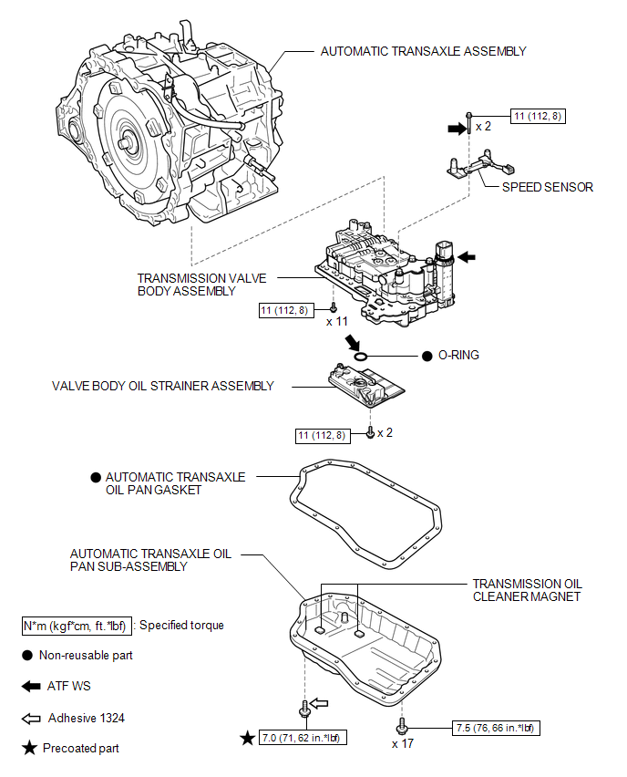
COMPONENTS
ILLUSTRATION
Removal
REMOVAL
PROCEDURE
1. REMOVE AUTOMATIC TRANSAXLE ASSEMBLY
HINT:
See the steps from "Remove Engine Assembly with transaxle" through "Remove Automatic
Transaxle Assembly" (See page .gif) ).
).
2. REMOVE AUTOMATIC TRANSAXLE OIL PAN SUB-ASSEMBLY
3. REMOVE VALVE BODY OIL STRAINER ASSEMBLY
4. REMOVE TRANSMISSION VALVE BODY ASSEMBLY
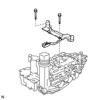
5. REMOVE SPEED SENSOR
(a) Disconnect the speed sensor connector.
|
(b) Remove the 2 bolts and speed sensor from the transmission valve body assembly. |
|
Installation
INSTALLATION
PROCEDURE
1. INSTALL SPEED SENSOR
|
(a) Coat the 2 bolts with ATF. |
|
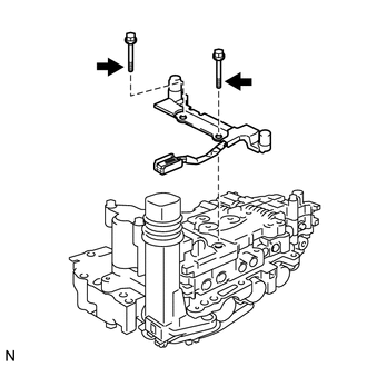
(b) Install the speed sensor to the transmission valve body assembly with the 2 bolts.
Torque:
11 N·m {112 kgf·cm, 8 ft·lbf}
(c) Connect the speed sensor connector.
2. INSTALL TRANSMISSION VALVE BODY ASSEMBLY
.gif)
3. INSTALL VALVE BODY OIL STRAINER ASSEMBLY
4. INSTALL AUTOMATIC TRANSAXLE OIL PAN SUB-ASSEMBLY
5. INSTALL AUTOMATIC TRANSAXLE ASSEMBLY
HINT:
See the steps from "Install Automatic Transaxle Assembly" through "Install Engine
Assembly with Transaxle" (See page ).
 Reassembly
REASSEMBLY
PROCEDURE
1. INSTALL SHIFT LOCK CONTROL COMPUTER SUB-ASSEMBLY
(a) Engage the 3 claws to install the shift lock control computer sub-assembly.
...
 Speed Sensor(when Using The Engine Support Bridge)
Components
COMPONENTS
ILLUSTRATION
Removal
REMOVAL
PROCEDURE
1. REMOVE TRANSMISSION VALVE BODY ASSEMBLY
See page
2. REMOVE SPEED SENSOR
(a) Disconnect the speed sensor connector.
...
Other materials about Toyota Venza:
Emission Control System
Parts Location
PARTS LOCATION
ILLUSTRATION
On-vehicle Inspection
ON-VEHICLE INSPECTION
PROCEDURE
1. INSPECT FUEL CUT-OFF RPM
(a) Increase the engine speed to at least 3500 rpm.
(b) Use a sound scope to check for injector operating soun ...
Removal
REMOVAL
PROCEDURE
1. DISCONNECT CABLE FROM NEGATIVE BATTERY TERMINAL
NOTICE:
When disconnecting the cable, some systems need to be initialized after the cable
is reconnected (See page ).
2. REMOVE COOL AIR INTAKE DUCT SEAL
3. REMOVE NO. 1 ENGINE CO ...
Reassembly
REASSEMBLY
PROCEDURE
1. INSTALL NO. 1 CENTER SUPPORT BEARING ASSEMBLY
(a) Set the No. 1 center support bearing on the intermediate shaft as
shown in the illustration.
NOTICE:
Make sure to install the bearing in the correct position.
...

0.1732