Toyota Venza: Removal
REMOVAL
PROCEDURE
1. DISCONNECT CABLE FROM NEGATIVE BATTERY TERMINAL
NOTICE:
When disconnecting the cable, some systems need to be initialized after the cable
is reconnected (See page .gif) ).
).
2. REMOVE COOL AIR INTAKE DUCT SEAL
3. REMOVE NO. 1 ENGINE COVER SUB-ASSEMBLY
4. REMOVE V-RIBBED BELT
HINT:
See page
5. REMOVE WIRE HARNESS CLAMP BRACKET
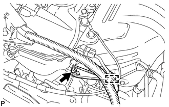
(a) Detach the wire harness clamp from the clamp bracket.
(b) Remove the bolt and clamp bracket.
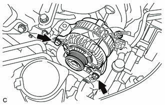
6. REMOVE GENERATOR ASSEMBLY
|
(a) Disconnect the generator connector. |
|
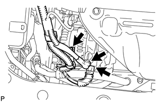
(b) Remove the terminal cap.
(c) Remove the nut and disconnect the generator wire.
(d) Remove the bolt and wire harness clamp bracket.
|
(e) Remove the 2 bolts and generator. |
|
 Components
COMPONENTS
ILLUSTRATION
ILLUSTRATION
ILLUSTRATION
...
 Disassembly
DISASSEMBLY
PROCEDURE
1. REMOVE GENERATOR PULLEY CAP
(a) Using a screwdriver, puncture the center of the generator pulley
cap and pry it off.
NOTICE:
Do not reuse the generator ...
Other materials about Toyota Venza:
Removal
REMOVAL
CAUTION / NOTICE / HINT
NOTICE:
w/Camera mirror:The timing of the change between high beams and low beams differs
depending on the light transmission rate of the glass. For this reason, when replacing
the windshield, replace it with an original ...
Disposal
DISPOSAL
CAUTION / NOTICE / HINT
CAUTION:
Before performing pre-disposal deployment of any SRS part, review and closely
follow all applicable environmental and hazardous material regulations. Pre-disposal
deployment may be considered hazardous material ...
Components
COMPONENTS
ILLUSTRATION
ILLUSTRATION
ILLUSTRATION
ILLUSTRATION
ILLUSTRATION
...

0.1705