Toyota Venza: Reassembly
REASSEMBLY
PROCEDURE
1. INSTALL NO. 1 CENTER SUPPORT BEARING ASSEMBLY
|
(a) Set the No. 1 center support bearing on the intermediate shaft as shown in the illustration. NOTICE: Make sure to install the bearing in the correct position. |
|
(b) Install a new washer to the intermediate shaft.
|
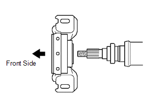
(c) Align the matchmarks on the universal joint flange and intermediate shaft and place the flange on the shaft. Text in Illustration
|
|
.png)
|
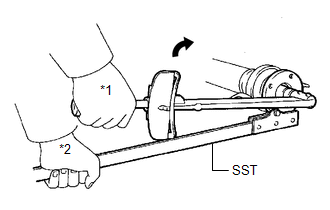
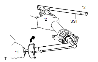
(d) Using SST to hold the universal joint flange, press the No. 1 center support bearing assembly into position by tightening a new nut and washer. SST: 09330-00021 Torque: 182 N·m {1851 kgf·cm, 134 ft·lbf} Text in Illustration
|
|
(e) Loosen the nut.
(f) Tighten the nut again.
Torque:
69 N·m {701 kgf·cm, 51 ft·lbf}
|
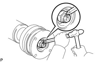
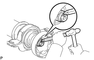
(g) Using a chisel and a hammer, stake the nut. |
|
2. INSTALL NO. 2 CENTER SUPPORT BEARING ASSEMBLY
|
(a) Set the No. 2 center support bearing on the intermediate shaft as shown in the illustration. NOTICE: Make sure to install the bearing in the correct position. |
|
(b) Install a new washer to the intermediate shaft.
|
(c) Align the matchmarks on the universal joint flange and intermediate shaft, and place the flange on the shaft. Text in Illustration
|
|
.png)
|
(d) Using SST to hold the universal joint flange, press the No. 2 center support bearing assembly into position by tightening a new nut and washer. SST: 09330-00021 Torque: 182 N·m {1851 kgf·cm, 134 ft·lbf} Text in Illustration
|
|
(e) Loosen the nut.
(f) Tighten the nut again.
Torque:
69 N·m {701 kgf·cm, 51 ft·lbf}
|
(g) Using a chisel and a hammer, stake the nut. |
|
3. INSTALL INTERMEDIATE SHAFT
|
(a) Align the matchmarks on the intermediate shaft and rear propeller shaft, and then install 2 washers and 6 bolts. Text in Illustration
|
|
.png)
(b) Using a hexagon wrench (6 mm), tighten the 6 bolts with 2 washers temporarily.
4. INSTALL PROPELLER SHAFT
(a) Align the matchmarks on the propeller shaft and the universal joint flange.
|
(b) Install the propeller shaft to the front flange with the 4 bolts, 4 washers and 4 nuts. Torque: 74 N·m {750 kgf·cm, 55 ft·lbf} NOTICE:
|
|
.png)
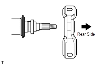
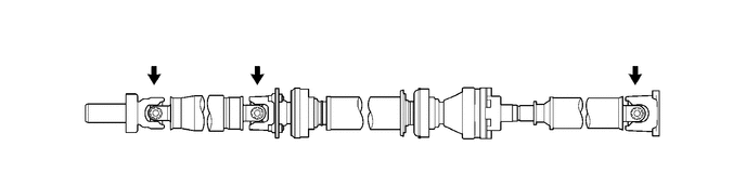
(c) Check that each joint of the propeller with center bearing shaft assembly is facing the direction shown in the illustration.
 Installation
INSTALLATION
PROCEDURE
1. TEMPORARILY TIGHTEN PROPELLER WITH CENTER BEARING SHAFT ASSEMBLY
(a) Remove SST from the transfer.
SST: 09325-20010
...
 Propeller Shaft System
Problem Symptoms Table
PROBLEM SYMPTOMS TABLE
HINT:
Use the table below to help determine the cause of problem symptoms. If multiple
suspected areas are listed, the potential causes of the symp ...
Other materials about Toyota Venza:
Dtc Check / Clear
DTC CHECK / CLEAR
1. CHECK FOR TRANSPONDER KEY ECU DTC
(a) Connect the Techstream to the DLC3.
(b) Turn the ignition switch to ON.
(c) Turn the Techstream on.
(d) Enter the following menus: Body Electrical / Immobiliser / Trouble Codes.
(e) Check the det ...
Brake Warning Light does not Come ON
DESCRIPTION
The skid control ECU is connected to the combination meter via CAN communication.
WIRING DIAGRAM
Refer to Brake Warning Light Remains ON (See page
).
PROCEDURE
1.
CHECK CAN COMMUNICATION SYSTEM
(a) Check if a ...
Adjustment
ADJUSTMENT
PROCEDURE
1. INSPECT SHIFT LEVER POSITION
(a) When moving the lever from P to R with the ignition switch ON and the brake
pedal depressed, make sure that the shift lever moves smoothly and moves correctly
into position.
(b) Start the engine ...

0.1342