Toyota Venza: Reassembly
REASSEMBLY
PROCEDURE
1. INSTALL SHIFT LOCK CONTROL COMPUTER SUB-ASSEMBLY
|
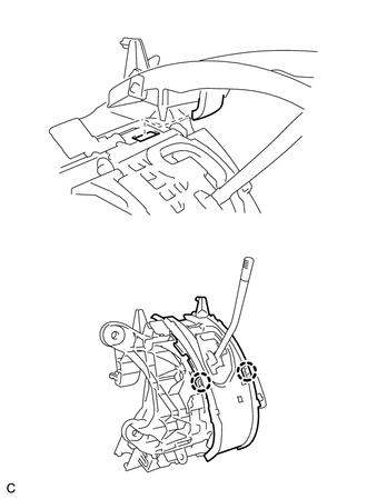
(a) Engage the 3 claws to install the shift lock control computer sub-assembly. |
|
.png)
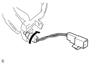
(b) Connect the connector.
2. INSTALL LOWER POSITION INDICATOR HOUSING
|
(a) Put the guide in position and engage the 2 claws to install the lower position indicator housing to the shift lock control unit assembly. NOTICE: Make sure that the claws are firmly engaged. |
|
3. INSTALL NO. 2 POSITION INDICATOR SLIDE COVER
(a) Install the No. 2 position indicator slide cover to the position indicator slide cover.
4. INSTALL POSITION INDICATOR SLIDE COVER
|
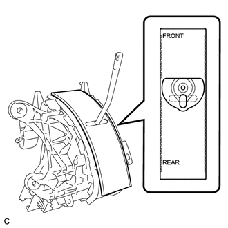
(a) Install the position indicator slide cover to the lower position indicator housing as shown in the illustration. |
|
5. INSTALL UPPER POSITION INDICATOR HOUSING
|
(a) Engage the 4 claws to install the upper position indicator housing to the lower position indicator housing. NOTICE: Make sure that the claws are firmly engaged. |
|
.png)
6. INSTALL POSITION INDICATOR LIGHT BULB
(a) Install the position indicator light bulb to the indicator light wire sub-assembly.
(b) Install the position indicator light cap to the position indicator light bulb.
7. INSTALL INDICATOR LIGHT WIRE SUB-ASSEMBLY
|
(a) Install the indicator light wire socket and connector to the position indicator light guide. |
|
8. INSTALL SHIFT LOCK RELEASE BUTTON
|
(a) Engage the 2 claws to install the shift lock release button and compression spring to the lower position indicator housing. NOTICE: Make sure that the claws are firmly engaged. |
|
.png)
9. INSTALL POSITION INDICATOR LIGHT GUIDE
|
(a) Engage the 4 claws to install the position indicator connector and position indicator light guide to the lower position indicator housing. NOTICE: Make sure that the claws are firmly engaged. |
|
.png)
10. INSTALL POSITION INDICATOR HOUSING SUB-ASSEMBLY
|
(a) Engage the 4 claws to install the position indicator housing sub-assembly to the lower position indicator housing. NOTICE: Make sure that the claws are firmly engaged. |
|
.png)
(b) Install the shift lever cap to the position indicator housing sub-assembly.
 Installation
INSTALLATION
PROCEDURE
1. INSTALL SHIFT LEVER ASSEMBLY
NOTICE:
Check that the park/neutral position switch and the shift lever are in neutral.
(a) Slide the slider of the transmission ...
 Speed Sensor(when Not Using The Engine Support Bridge)
Components
COMPONENTS
ILLUSTRATION
Removal
REMOVAL
PROCEDURE
1. REMOVE AUTOMATIC TRANSAXLE ASSEMBLY
HINT:
See the steps from "Remove Engine Assembly with transaxle" through &qu ...
Other materials about Toyota Venza:
Vehicle Speed Signal Error (Test Mode DTC) (C2191/91)
DESCRIPTION
The tire pressure warning ECU receives a vehicle speed signal from the combination
meter. This DTC is stored upon entering signal check mode (test mode), and cleared
when a vehicle speed signal of 20 km/h (12 mph) is detected for 3 seconds or ...
Automatic air conditioning system
Airflow and outlets are automatically adjusted according to the temperature
setting.
► Control panel
► Multi-information display (TFT type)
The settings display will differ according to the situation. If
is pressed while in automat ...
Removal
REMOVAL
PROCEDURE
1. DISCONNECT CABLE FROM NEGATIVE BATTERY TERMINAL
NOTICE:
When disconnecting the cable, some systems need to be initialized after the cable
is reconnected (See page ).
2. RECOVER REFRIGERANT FROM REFRIGERATION SYSTEM
3. REMOVE CO ...

0.1385