Toyota Venza: Sliding Roof does not Move by Operating Sliding Roof Control Switch
DESCRIPTION
The sliding roof ECU (sliding roof drive gear sub-assembly) receives switch slide and tilt signals and drives its built-in motor.
WIRING DIAGRAM
.png)
CAUTION / NOTICE / HINT
NOTICE:
- Inspect the fuses for circuits related to this system before performing the following inspection procedure.
- When the sliding roof ECU (sliding roof drive gear sub-assembly) is
reinstalled or replaced, the sliding roof drive gear sub-assembly must be
initialized (See page
.gif) ).
). - Since the sliding roof system uses LIN communication, first confirm
that there is no malfunction in the communication system by inspecting the
LIN communication functions in accordance with the How to Proceed with Troubleshooting
procedure (See page ). Then, conduct
the following inspection procedure.
PROCEDURE
|
1. |
PERFORM ACTIVE TEST USING TECHSTREAM (SLIDING ROOF OPERATION) |
(a) Connect the Techstream to the DLC3.
(b) Turn the ignition switch to ON.
(c) Turn the Techstream on.
(d) Enter the following menus: Body Electrical / Sliding Roof / Active Test.
(e) Perform the Active Test according to the display on the Techstream.
Sliding Roof (Sliding Roof ECU (Sliding Roof Drive Gear Sub-assembly))|
Tester Display |
Test Part |
Control Range |
Diagnostic Note |
|---|---|---|---|
|
Slide Roof |
Operate sliding roof |
CLOS/UP / OFF |
- |
|
Slide Roof |
Operate sliding roof |
OPN/DWN / OFF |
- |
OK:
Sliding roof operates normally.
| NG | .gif) |
GO TO STEP 3 |
|
.gif)
|
2. |
READ VALUE USING TECHSTREAM |
(a) Connect the Techstream to the DLC3.
(b) Turn the ignition switch to ON.
(c) Turn the Techstream on.
(d) Enter the following menus: Body Electrical / Sliding Roof / Data List.
(e) Read the Data List according to the display on the Techstream.
Sliding Roof (Sliding Roof ECU (Sliding Roof Drive Gear Sub-assembly))|
Tester Display |
Measurement Item/Range |
Normal Condition |
Diagnostic Note |
|---|---|---|---|
|
Open SW |
SLIDE OPEN switch signal/ON or OFF |
ON: SLIDE OPEN switch pressed OFF: SLIDE OPEN switch not pressed |
- |
|
Close SW |
SLIDE CLOSE switch signal/ON or OFF |
ON: SLIDE CLOSE switch pressed OFF: SLIDE CLOSE switch not pressed |
- |
|
Up SW |
TILT UP switch signal/ON or OFF |
ON: TILT UP switch pressed OFF: TILT UP switch not pressed |
- |
|
Down SW |
TILT DOWN switch signal/ON or OFF |
ON: TILT DOWN switch pressed OFF: TILT DOWN switch not pressed |
- |
OK:
The Techstream display changes according to switch operation as shown in the table.
| OK | |
REPLACE SLIDING ROOF ECU (SLIDING ROOF DRIVE GEAR SUB-ASSEMBLY) |
| NG | |
GO TO STEP 4 |
|
3. |
CHECK HARNESS AND CONNECTOR (SLIDING ROOF ECU - BATTERY, BODY GROUND) |
|
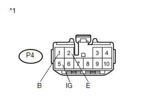
(a) Disconnect the P4 ECU connector. |
|
(b) Measure the voltage according to the value(s) in the table below.
Standard Voltage:
|
Tester Connection |
Condition |
Specified Condition |
|---|---|---|
|
P4-1 (B) - Body ground |
Always |
11 to 14 V |
|
P4-5 (IG) - Body ground |
Ignition switch ON |
11 to 14 V |
|
P4-5 (IG) - Body ground |
Ignition switch off |
Below 1 V |
(c) Measure the resistance according to the value(s) in the table below.
Standard Resistance:
|
Tester Connection |
Condition |
Specified Condition |
|---|---|---|
|
P4-2 (E) - Body ground |
Always |
Below 1 Ω |
|
*1 |
Front view of wire harness connector (to Sliding Roof ECU (Sliding Roof Drive Gear Sub-assembly)) |
| OK | |
REPLACE SLIDING ROOF ECU (SLIDING ROOF DRIVE GEAR SUB-ASSEMBLY) |
| NG | |
REPAIR OR REPLACE HARNESS OR CONNECTOR |
|
4. |
CHECK HARNESS AND CONNECTOR (SLIDING ROOF ECU - SLIDING ROOF SWITCH ASSEMBLY) |
|
(a) Disconnect the P6 switch connector. |
|
.png)
(b) Disconnect the P4 ECU connector.
(c) Measure the resistance according to the value(s) in the table below.
Standard Resistance:
|
Tester Connection |
Condition |
Specified Condition |
|---|---|---|
|
P4-9 (CLS) - P6-2 (CLS) |
Always |
Below 1 Ω |
|
P4-9 (CLS) - Body ground |
Always |
10 kΩ or higher |
|
P4-7 (OPN) - P6-3 (OPN) |
Always |
Below 1 Ω |
|
P4-7 (OPN) - Body ground |
Always |
10 kΩ or higher |
|
P4-8 (DWN) - P6-4 (DOWN) |
Always |
Below 1 Ω |
|
P4-8 (DWN) - Body ground |
Always |
10 kΩ or higher |
|
P4-10 (UP) - P6-5 (UP) |
Always |
Below 1 Ω |
|
P4-10 (UP) - Body ground |
Always |
10 kΩ or higher |
|
P6-1 (GND) - Body ground |
Always |
Below 1 Ω |
|
P4-2 (E) - Body ground |
Always |
Below 1 Ω |
|
*1 |
Front view of wire harness connector (to Sliding Roof ECU (Sliding Roof Drive Gear Sub-assembly)) |
|
*2 |
Front view of wire harness connector (to Sliding Roof Switch (Roof Console Box Assembly)) |
| NG | |
REPAIR OR REPLACE HARNESS OR CONNECTOR |
|
|
5. |
INSPECT SLIDING ROOF SWITCH (ROOF CONSOLE BOX ASSEMBLY) |
|
(a) Remove the sliding roof switch (roof console box assembly) (See page
|
|
.png)
(b) Measure the resistance according to the value(s) in the table below.
Standard Resistance:
|
Tester Connection |
Condition |
Specified Condition |
|---|---|---|
|
P6-4 (DOWN) - P6-1 (GND) |
TILT DOWN switch is pressed |
Below 1 Ω |
|
P6-4 (DOWN) - P6-1 (GND) |
TILT DOWN switch is not pressed |
10 kΩ or higher |
|
P6-5 (UP) - P6-1 (GND) |
TILT UP switch is pressed |
Below 1 Ω |
|
P6-5 (UP) - P6-1 (GND) |
TILT UP switch is not pressed |
10 kΩ or higher |
|
P6-2 (CLS) - P6-1 (GND) |
SLIDE CLOSE switch is pressed |
Below 1 Ω |
|
P6-2 (CLS) - P6-1 (GND) |
SLIDE CLOSE switch is not pressed |
10 kΩ or higher |
|
P6-3 (OPN) - P6-1 (GND) |
SLIDE OPEN switch is pressed |
Below 1 Ω |
|
P6-3 (OPN) - P6-1 (GND) |
SLIDE OPEN switch is not pressed |
10 kΩ or higher |
|
*1 |
Component without harness connected Sliding Roof Switch (Roof Console Box Assembly) |
| OK | |
REPLACE SLIDING ROOF ECU (SLIDING ROOF DRIVE GEAR SUB-ASSEMBLY) |
| NG | |
REPLACE SLIDING ROOF SWITCH (ROOF CONSOLE BOX ASSEMBLY) |
 Sensor (Motor) Failure (B2341,B2344)
DESCRIPTION
When the sliding roof ECU (sliding roof drive gear sub-assembly) detects a motor
malfunction and the sliding roof operation is stopped, DTC B2341 is output.
When the sliding roof ECU ( ...
 Window / Glass
...
Other materials about Toyota Venza:
Removal
REMOVAL
PROCEDURE
1. DISCONNECT CABLE FROM NEGATIVE BATTERY TERMINAL
NOTICE:
When disconnecting the cable, some systems need to be initialized after the cable
is reconnected (See page ).
2. REMOVE UPPER CONSOLE PANEL SUB-ASSEMBLY (w/o Seat Heater Syste ...
Problem Symptoms Table
PROBLEM SYMPTOMS TABLE
HINT:
Use the table below to help determine the cause of problem symptoms.
If multiple suspected areas are listed, the potential causes of the symptoms
are listed in order of probability in the "Suspected Area" ...
Engine does not Start
DESCRIPTION
1. ENGINE START SYSTEM FUNCTION
(a) If the engine switch is pressed with the shift lever in P or N and the brake
pedal depressed, the power management control ECU determines that this is an engine
start request.
(b) The certification ECU (sm ...

0.1766