Toyota Venza: Relay
On-vehicle Inspection
ON-VEHICLE INSPECTION
PROCEDURE
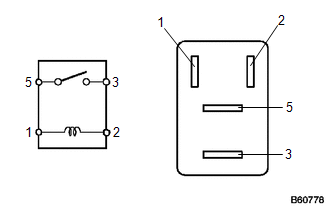
1. INSPECT STARTER RELAY
|
(a) Measure the resistance according to the value(s) in the table below. Standard Resistance:
If the resistance is not as specified, replace the relay. |
|
 Ignition Switch
Components
COMPONENTS
ILLUSTRATION
Removal
REMOVAL
PROCEDURE
1. REMOVE LOWER STEERING COLUMN COVER
2. REMOVE UPPER STEERING COLUMN COVER
3. REMOVE IGNITION SWITCH
(a) R ...
 Starter
...
Other materials about Toyota Venza:
Diagnosis System
DIAGNOSIS SYSTEM
1. DESCRIPTION
(a) The certification ECU (smart key ECU assembly) and ECM control the vehicle
engine immobiliser system functions. Engine immobiliser system data and Diagnostic
Trouble Codes (DTCs) can be read through the vehicle Data Li ...
Motor Circuit Malfunction (C1521,C1531-C1534,C1554)
DESCRIPTION
If the power steering ECU detects these DTCs, it will shut off the motor relay
circuit (built into the power steering ECU) and stop power assist. However, power
assist continues if DTC C1533 or C1534 is stored.
DTC No.
D ...
Inspection
INSPECTION
PROCEDURE
1. INSPECT OUTER REAR VIEW MIRROR ASSEMBLY RH
(a) Check the operation of the mirror surface.
(1) Disconnect the outer rear view mirror assembly RH connector.
(2) Apply battery ...

0.1507