Toyota Venza: SFR Solenoid Circuit (C0226/21,C0236/22,C0246/23,C0256/24,C1225/25-C1228/28)
DESCRIPTION
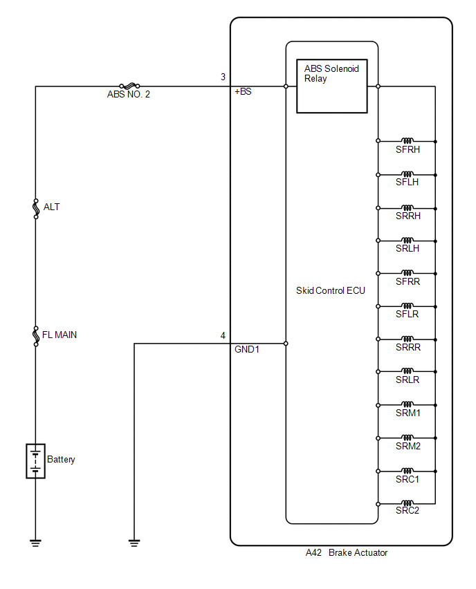
These solenoids turn on when signals are received from the skid control ECU and they control the pressure acting on the wheel cylinders to control the braking force.
|
DTC Code |
DTC Detection Condition |
Trouble Area |
|---|---|---|
|
C0226/21 C0236/22 C0246/23 C0256/24 C1225/25 C1226/26 C1227/27 C1228/28 |
Solenoid valve signal does not match the check result. |
|
WIRING DIAGRAM
PROCEDURE
|
1. |
RECONFIRM DTC |
HINT:
These codes are detected when a problem is determined in the brake actuator assembly.
The solenoid circuits are in the brake actuator assembly.
Therefore, solenoid circuit inspection and solenoid unit inspection cannot be performed. Be sure to check if any DTC is output before replacing the brake actuator assembly.
(a) Clear the DTCs (See page .gif) ).
).
(b) Start the engine.
(c) Drive the vehicle at a speed of 20 km/h (12 mph) or more.
(d) Check if the same DTC is recorded (See page
).
|
Result |
Proceed to |
|---|---|
|
DTCs (C0226/21, C0236/22, C0246/23, C0256/24, C1225/25, C1226/26, C1227/27 and C1228/28) are not output |
A |
|
DTCs (C0226/21, C0236/22, C0246/23, C0256/24, C1225/25, C1226/26, C1227/27 and/or C1228/28) are output |
B |
HINT:
- If a speed signal of 15 km/h (9 mph) or more is input to the skid control ECU, with the ignition switch ON and the stop light switch off, the ECU performs self diagnosis of the motor and solenoid circuits.
- If the normal system code is output (the trouble code is not output), slightly jiggle the connectors, wire harness, and fuses of the brake actuator assembly. Make sure that no DTCs are output.
- If any DTCs are output while jiggling a connector or wire harness of the brake actuator assembly (skid control ECU), inspect and repair the connector or wire harness.
- It is suspected that the DTCs were output due to a bad connection of the connector terminal.
| A | .gif) |
CHECK FOR INTERMITTENT PROBLEMS |
| B | |
REPLACE BRAKE ACTUATOR ASSEMBLY |
 Open or Short Circuit in ABS Motor Relay Circuit (C0273/13)
DESCRIPTION
The ABS motor relay supplies power to the ABS pump motor. While the ABS is activated,
the ECU turns the motor relay on and operates the ABS pump motor.
If the voltage supplied to the m ...
 ABS Control System Malfunction (43)
DESCRIPTION
This DTC is output when the VSC system detects a malfunction in the ABS control
system.
DTC Code
DTC Detection Condition
Trouble Area
...
Other materials about Toyota Venza:
Problem Symptoms Table
PROBLEM SYMPTOMS TABLE
HINT:
Use the table below to help determine the cause of problem symptoms. If multiple
suspected areas are listed, the potential causes of the symptoms are listed in order
of probability in the "Suspected Area" column of ...
Air Conditioning Pressure Sensor
Components
COMPONENTS
ILLUSTRATION
Installation
INSTALLATION
PROCEDURE
1. INSTALL AIR CONDITIONING PRESSURE SENSOR
(a) Sufficiently apply compressor oil to a new air conditioning pressure
sensor.
Compressor oil:
ND-OIL 8 or e ...
Evaporator Temperature Sensor Circuit (B1413/13)
DESCRIPTION
The evaporator temperature sensor is installed on the evaporator in the air conditioning
unit to detect the cooled air temperature that has passed through the evaporator
and to control the air conditioning. It sends appropriate signals to the ...

0.1285