
Toyota Venza: Seat Heater Switch
Components
COMPONENTS
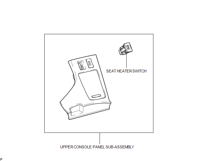
ILLUSTRATION
Removal
REMOVAL
PROCEDURE
1. REMOVE UPPER CONSOLE PANEL SUB-ASSEMBLY
.gif)
2. REMOVE SEAT HEATER SWITCH
|
(a) Disengage the 2 claws and remove the seat heater switch as shown in the illustration. |
|

Inspection
INSPECTION
PROCEDURE
1. INSPECT SEAT HEATER SWITCH
|
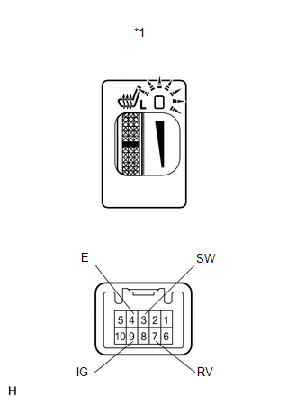
(a) Inspect the driver side seat heater switch operation. (1) Measure the resistance according to the value(s) in the table below. Standard Resistance:
If the result is not as specified, replace the switch. (2) Turn the seat heater switch on and check if the seat heater switch indicator comes on. OK:
If the result is not as specified, replace the switch. |
|
|
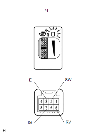
(b) Inspect the front passenger side seat heater switch operation. (1) Measure the resistance according to the value(s) in the table below. Standard Resistance:
If the result is not as specified, replace the switch. (2) Turn the seat heater switch on and check if the seat heater switch indicator comes on. OK:
If the result is not as specified, replace the switch. |
|
|
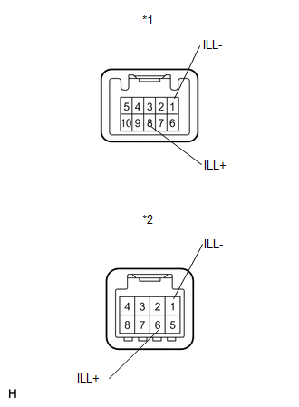
(c) Check if the seat heater switch indicator comes on. OK: Driver Side
If the result is not as specified, replace the switch. |
|
Installation
INSTALLATION
PROCEDURE
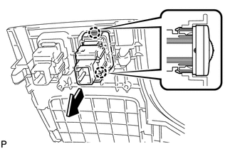
1. INSTALL SEAT HEATER SWITCH
|
(a) Engage the 2 claws and install the seat heater switch as shown in the illustration. |
|
2. INSTALL UPPER CONSOLE PANEL SUB-ASSEMBLY
.gif)
 Seat Heater Control
Components
COMPONENTS
ILLUSTRATION
Installation
INSTALLATION
PROCEDURE
1. INSTALL SEAT HEATER CONTROL SUB-ASSEMBLY
(a) Engage the clamp and install the seat heater control sub- ...
 Seat Heater System
Precaution
PRECAUTION
1. NOTICE FOR INITIALIZATION
HINT:
When disconnecting the cable from the negative (-) battery terminal, initialize
the following systems after the cable is reconnected.
...
Other materials about Toyota Venza:
Knock Sensor 1 Circuit Low Input (Bank 1 or Single Sensor) (P0327,P0328)
DESCRIPTION
Flat-type knock sensors (non-resonant type) have structures that can detect vibrations
between approximately 5 and 15 kHz.
Knock sensors are fitted onto the engine block to detect engine knocking.
The knock sensor contains a piezoelectric elem ...
Inspection
INSPECTION
PROCEDURE
1. INSPECT PAD LINING THICKNESS
(a) Using a ruler, measure the pad lining thickness.
Text in Illustration
*1
Ruler
Standard thickness of a new pad:
10.0 mm (0.394 ...
Removal
REMOVAL
PROCEDURE
1. ALIGN FRONT WHEELS FACING STRAIGHT AHEAD
2. DISCONNECT CABLE FROM NEGATIVE BATTERY TERMINAL
CAUTION:
Wait at least 90 seconds after disconnecting the cable from the negative (-)
battery terminal to disable the SRS system.
NOTICE:
...

0.1288