Toyota Venza: Seat Heater Control
Components
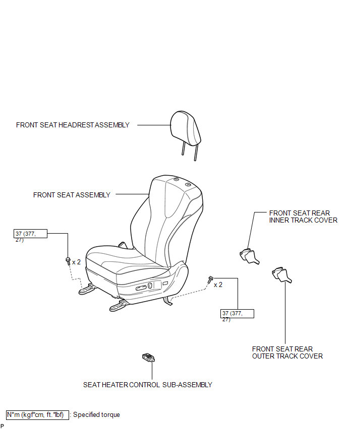
COMPONENTS
ILLUSTRATION
Installation
INSTALLATION
PROCEDURE
1. INSTALL SEAT HEATER CONTROL SUB-ASSEMBLY
|
(a) Engage the clamp and install the seat heater control sub-assembly. |
|
(b) Connect the connector.
2. INSTALL FRONT SEAT ASSEMBLY
.gif)
3. INSTALL FRONT SEAT REAR INNER TRACK COVER
4. INSTALL FRONT SEAT REAR OUTER TRACK COVER
5. INSTALL FRONT SEAT HEADREST ASSEMBLY
6. INSPECT FRONT SEAT ASSEMBLY
7. INSPECT SRS WARNING LIGHT
(See page )
Removal
REMOVAL
PROCEDURE
1. REMOVE FRONT SEAT HEADREST ASSEMBLY
2. REMOVE FRONT SEAT REAR OUTER TRACK COVER
.gif)
3. REMOVE FRONT SEAT REAR INNER TRACK COVER
4. REMOVE FRONT SEAT ASSEMBLY
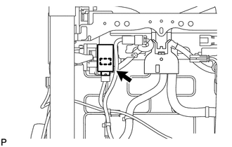
5. REMOVE SEAT HEATER CONTROL SUB-ASSEMBLY
|
(a) Disconnect the connector. |
|
.png)
(b) Disengage the clamp and remove the seat heater control sub-assembly.
 Installation
INSTALLATION
PROCEDURE
1. INSTALL REAR SEAT ASSEMBLY RH
(a) Place the rear seat assembly RH in the cabin.
NOTICE:
Be careful not to damage the vehicle body.
(b) Temporarily install th ...
 Seat Heater Switch
Components
COMPONENTS
ILLUSTRATION
Removal
REMOVAL
PROCEDURE
1. REMOVE UPPER CONSOLE PANEL SUB-ASSEMBLY
2. REMOVE SEAT HEATER SWITCH
(a) Disengage the 2 claws and remove th ...
Other materials about Toyota Venza:
Diagnosis Circuit
DESCRIPTION
The headlight leveling ECU assembly outputs DTC information to the Techstream
via this circuit.
WIRING DIAGRAM
PROCEDURE
1.
CHECK HARNESS AND CONNECTOR (DLC3 - HEADLIGHT LEVELING ECU ASSEMBLY)
(a) Disconnect ...
Mechanical System Tests
MECHANICAL SYSTEM TESTS
1. STALL SPEED TEST
HINT:
This test is to check the overall performance of the engine and transaxle.
CAUTION:
Driving test should be done on a paved surface (a surface that is not
slippery).
To ensure safety, perfor ...
Multi-information display (TFT type)
The multi-information display presents the driver with a variety of driving-related
data, including the clock and current outside temperature.
• Clock
Indicates and sets the time.
• Outside temperature
Indicates the outside temperature.
The temper ...

0.1607