Toyota Venza: Seat Heater System
Precaution
PRECAUTION
1. NOTICE FOR INITIALIZATION
HINT:
When disconnecting the cable from the negative (-) battery terminal, initialize the following systems after the cable is reconnected.
|
System Name |
See procedure |
|---|---|
|
Back Door Closer System |
|
|
Power Back Door System |
.gif)
2. IGNITION SWITCH EXPRESSIONS
HINT:
The type of ignition switch used on this model differs according to the specifications of the vehicle. The expressions listed in the table below are used in this section.
|
Expression |
Ignition Switch (position) |
Engine Switch (condition) |
|---|---|---|
|
Ignition Switch off |
LOCK |
Off |
|
Ignition Switch ON |
ON |
On (IG) |
|
Ignition Switch ACC |
ACC |
On (ACC) |
|
Engine Start |
START |
Start |
Parts Location
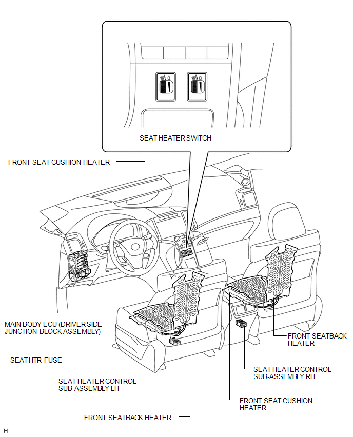
PARTS LOCATION
ILLUSTRATION
Problem Symptoms Table
PROBLEM SYMPTOMS TABLE
Seat Heater System|
Symptom |
Suspected Area |
See page |
|---|---|---|
|
Drivers seat heater does not warm up |
SEAT HTR fuse |
- |
|
Seat heater switch LH |
|
|
|
Front seat cushion heater (for power seat) |
|
|
|
Front seatback heater (for power seat) |
|
|
|
Seat heater controller |
- |
|
|
Wire harness or connector |
- |
|
|
Passengers seat heater does not warm up |
SEAT HTR fuse |
- |
|
Seat heater switch RH |
|
|
|
Front seat cushion heater (for power seat) |
|
|
|
Front seatback heater (for power seat) |
|
|
|
Seat heater controller |
- |
|
|
Wire harness or connector |
- |
.gif)
System Diagram
SYSTEM DIAGRAM
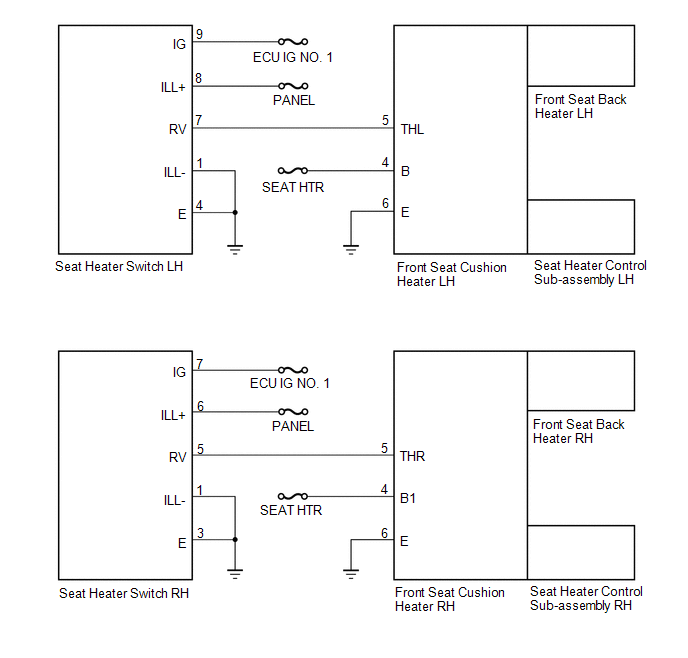
 Seat Heater Switch
Components
COMPONENTS
ILLUSTRATION
Removal
REMOVAL
PROCEDURE
1. REMOVE UPPER CONSOLE PANEL SUB-ASSEMBLY
2. REMOVE SEAT HEATER SWITCH
(a) Disengage the 2 claws and remove th ...
 Seat Memory Switch
Components
COMPONENTS
ILLUSTRATION
Removal
REMOVAL
PROCEDURE
1. REMOVE FRONT DOOR INSIDE HANDLE BEZEL PLUG LH
2. REMOVE POWER WINDOW REGULATOR MASTER SWITCH ASSEMBLY WITH FRONT DOOR AR ...
Other materials about Toyota Venza:
Internal Control Module A/D Processing Performance (P060B)
MONITOR DESCRIPTION
This DTC is stored when a communication error occurs in the ECM.
DTC Code
DTC Detection Condition
Trouble Area
P060B
There is an ECM main CPU communication error (1 trip detecti ...
Power Window Master Switch
Components
COMPONENTS
ILLUSTRATION
Removal
REMOVAL
PROCEDURE
1. REMOVE POWER WINDOW REGULATOR MASTER SWITCH ASSEMBLY WITH FRONT DOOR ARMREST
BASE PANEL
2. REMOVE POWER WINDOW REGULATOR MASTER SWITCH ASSEMBLY
(a) Remove the 3 screw ...
Transmission Fluid Temperature Sensor "A" Circuit Low Input (P0712,P0713)
DESCRIPTION
The Automatic Transmission Fluid (ATF) temperature sensor converts the fluid
temperature into a resistance value for use by the TCM.
The TCM applies a voltage to the temperature sensor through terminal THO1 of
the TCM.
The sensor resistanc ...

0.1212