Toyota Venza: Removal
REMOVAL
PROCEDURE
1. PRECAUTION
NOTICE:
After turning the ignition switch off, waiting time may be required before disconnecting
the cable from the negative (-) battery terminal. Therefore, make sure to read the
disconnecting the cable from the negative (- ) battery terminal notices before proceeding
with work (See page .gif) ).
).
2. DISCONNECT CABLE FROM NEGATIVE BATTERY TERMINAL
CAUTION:
Wait at least 90 seconds after disconnecting the cable from the negative (-)
battery terminal to disable the SRS system (See page
).
NOTICE:
When disconnecting the cable, some systems need to be initialized after the cable
is reconnected (See page ).
3. REMOVE FRONT DOOR INSIDE HANDLE BEZEL PLUG
4. REMOVE POWER WINDOW REGULATOR MASTER SWITCH ASSEMBLY WITH FRONT DOOR ARMREST BASE PANEL (for Driver Side)
5. REMOVE POWER WINDOW REGULATOR SWITCH ASSEMBLY WITH FRONT DOOR ARMREST BASE PANEL (for Front Passenger Side)
6. REMOVE COURTESY LIGHT ASSEMBLY
7. REMOVE FRONT DOOR TRIM BOARD SUB-ASSEMBLY
8. REMOVE FRONT DOOR INSIDE HANDLE SUB-ASSEMBLY
9. REMOVE DOOR SIDE AIRBAG SENSOR
10. REMOVE OUTER MIRROR CONTROL ECU ASSEMBLY (w/ Memory)
11. REMOVE FRONT DOOR SERVICE HOLE COVER
12. REMOVE OUTER REAR VIEW MIRROR ASSEMBLY
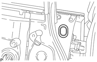
|
(a) Remove the hole plug. |
|
|
(b) Disconnect the connector. |
|
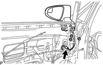
(c) Remove the 3 nuts.
|
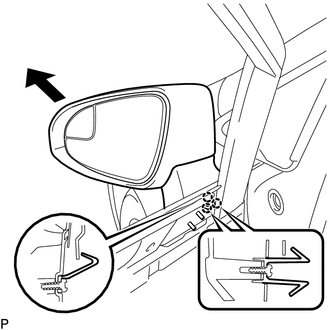
(d) Disengage the 3 claws and remove the outer rear view mirror assembly as shown in the illustration. |
|
 Components
COMPONENTS
ILLUSTRATION
ILLUSTRATION
ILLUSTRATION
...
 Disassembly
DISASSEMBLY
PROCEDURE
1. REMOVE OUTER MIRROR
2. REMOVE OUTER MIRROR LIGHT ASSEMBLY
3. REMOVE OUTER MIRROR COVER
4. REMOVE SIDE TURN SIGNAL LIGHT ASSEMBLY
...
Other materials about Toyota Venza:
Components
COMPONENTS
ILLUSTRATION
ILLUSTRATION
ILLUSTRATION
ILLUSTRATION
ILLUSTRATION
...
On-vehicle Inspection
ON-VEHICLE INSPECTION
PROCEDURE
1. INSPECT PARK/NEUTRAL POSITION SWITCH ASSEMBLY OPERATION
(a) Apply the parking brake.
(b) Turn the ignition switch to ON.
(c) Depress the brake pedal and check that the engine starts when the shift lever
is in N or P, b ...
Reassembly
REASSEMBLY
PROCEDURE
1. PRECAUTION
NOTICE:
After turning the ignition switch off, waiting time may be required before disconnecting
the cable from the negative (-) battery terminal. Therefore, make sure to read the
disconnecting the cable from the nega ...

0.1548