Toyota Venza: Rocker Panel Moulding
Components
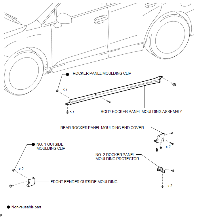
COMPONENTS
ILLUSTRATION
Removal
REMOVAL
PROCEDURE
1. REMOVE FRONT FENDER OUTSIDE MOULDING
.gif)
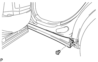
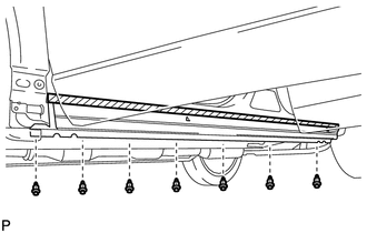
2. REMOVE NO. 2 ROCKER PANEL MOULDING PROTECTOR
3. REMOVE REAR ROCKER PANEL MOULDING END COVER
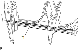
4. REMOVE BODY ROCKER PANEL MOULDING ASSEMBLY
|
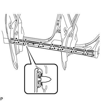
(a) Put protective tape around the body rocker panel moulding assembly. Text in Illustration
|
|
|
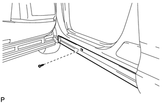
(b) Remove the screw. |
|
|
(c) Remove the grommet. |
|
|
(d) Remove the 7 clips. |
|
|
(e) Disengage the 7 clips to remove the body rocker panel moulding assembly. |
|
(f) Remove the 7 clips (rocker panel moulding clip).
Installation
INSTALLATION
PROCEDURE
1. INSTALL BODY ROCKER PANEL MOULDING ASSEMBLY
(a) Install 7 new clips (rocker panel moulding clip) to the body rocker panel moulding assembly.
|
(b) Engage the 7 clips to install the body rocker panel moulding assembly. |
|
.png)
|
(c) Install the screw. |
|
.png)
|
(d) Install the grommet. |
|
.png)
|
(e) Install the 7 clips. |
|
.png)
2. INSTALL REAR ROCKER PANEL MOULDING END COVER
.gif)
3. INSTALL NO. 2 ROCKER PANEL MOULDING PROTECTOR
4. INSTALL FRONT FENDER OUTSIDE MOULDING
 Rear Wheel House Plate
Components
COMPONENTS
ILLUSTRATION
Installation
INSTALLATION
PROCEDURE
1. INSTALL NO. 2 ROCKER PANEL MOULDING PROTECTOR
(a) Install the No. 2 rocker panel moulding protector wi ...

Other materials about Toyota Venza:
Terminals Of Ecu
TERMINALS OF ECU
1. CHECK ENGINE SWITCH
(a) Disconnect the D13 engine switch connector.
(b) Measure the resistance according to the value(s) in the table below.
HINT:
Measure the values on the wire harness side with connector disconnected.
T ...
Disassembly
DISASSEMBLY
PROCEDURE
1. REMOVE ENGINE COVER JOINT
(a) Remove the 3 joints.
2. REMOVE SPARK PLUG
3. REMOVE CAMSHAFT TIMING OIL CONTROL VALVE ASSEMBLY (for Intake Side)
4. REMOVE CAMSHAFT TIM ...
Precaution
PRECAUTION
1. PRECAUTION FOR DISCONNECTING CABLE FROM NEGATIVE BATTERY TERMINAL
NOTICE:
When disconnecting the cable from the negative (-) battery terminal, initialize
the following system after the terminal is reconnected:
System Name
...

0.1133