Toyota Venza: Driver Side Door Entry Lock and Unlock Functions do not Operate
DESCRIPTION
When the entry lock and unlock functions do not operate only for the driver door, an error in output request codes from the driver door or malfunction in the front door outside handle assembly is suspected. If the entry functions for the other doors operate normally, then the communication circuit between the key and door control receiver assembly is functioning normally. In this case, radio wave interference or a malfunction in the request code sending circuit (from the certification ECU (smart key ECU assembly) to the front door outside handle assembly (for driver side)) is suspected.
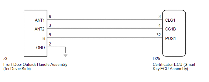
WIRING DIAGRAM
CAUTION / NOTICE / HINT
NOTICE:
- The smart key system (for entry function) uses a multiplex communication
system (LIN communication system) and CAN communication system. Inspect
the communication function by following How to Proceed with Troubleshooting
(See page
.gif) ). Troubleshoot the smart
). Troubleshoot the smart
key system (for entry function) after confirming that the communication system is functioning properly. - Confirm that another key is not in the cabin.
PROCEDURE
|
1. |
CHECK POWER DOOR LOCK OPERATION |
(a) When the door control switch on the master switch assembly is operated, check
that the doors unlock and lock according to switch operation (See page
).
OK:
Door locks operate normally.
| NG | .gif) |
GO TO POWER DOOR LOCK CONTROL SYSTEM (Proceed to Problem Symptoms Table) |
|
.gif)
|
2. |
CHECK WAVE ENVIRONMENT |
|
(a) Bring the key near the front door outside handle assembly (for driver side), and perform a driver door entry lock and unlock operation check. NOTICE: If the key is brought within 0.2 m (0.656 ft.) of the door outside handle assembly, communication is not possible. HINT:
OK: Entry functions operate normally. |
|
.png)
| OK | |
AFFECTED BY WAVE INTERFERENCE |
|
|
3. |
CHECK HARNESS AND CONNECTOR (CERTIFICATION ECU - FRONT DOOR OUTSIDE HANDLE) |
(a) Disconnect the certification ECU (smart key ECU assembly) connector.
|
(b) Disconnect the front door outside handle assembly (for driver side) connector. |
|
(c) Measure the resistance according to the value(s) in the table below.
Standard Resistance:
|
Tester Connection |
Condition |
Specified Condition |
|---|---|---|
|
D25-3 (CLG1) - z3-6 (ANT1) |
Always |
Below 1 Ω |
|
D25-4 (CG1B) - z3-3 (ANT2) |
Always |
Below 1 Ω |
|
D25-32 (POS1) - z3-5 (B) |
Always |
Below 1 Ω |
|
D25-3 (CLG1) - Body ground |
Always |
10 kΩ or higher |
|
D25-4 (CG1B) - Body ground |
Always |
10 kΩ or higher |
|
D25-32 (POS1) - Body ground |
Always |
10 kΩ or higher |
|
z3-6 (ANT1) - Body ground |
Always |
10 kΩ or higher |
|
z3-3 (ANT2) - Body ground |
Always |
10 kΩ or higher |
|
z3-5 (B) - Body ground |
Always |
10 kΩ or higher |
|
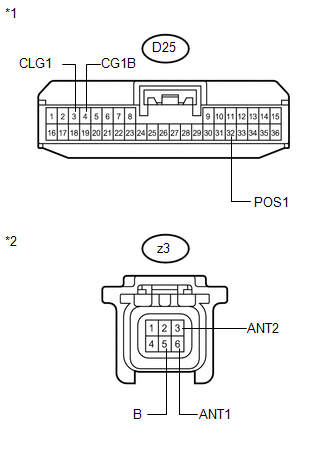
*1 |
Front view of wire harness connector (to Certification ECU (Smart Key ECU Assembly)) |
|
*2 |
Front view of wire harness connector (to Front Door Outside Handle Assembly (for Driver Side)) |
| NG | |
REPAIR OR REPLACE HARNESS OR CONNECTOR |
|
|
4. |
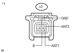
CHECK HARNESS AND CONNECTOR (FRONT DOOR OUTSIDE HANDLE - BODY GROUND) |
|
(a) Measure the resistance according to the value(s) in the table below. Standard Resistance:
|
|
.png)
| NG | |
REPAIR OR REPLACE HARNESS OR CONNECTOR |
|
|
5. |
INSPECT FRONT DOOR OUTSIDE HANDLE ASSEMBLY (DOOR OSCILLATOR, LOCK/UNLOCK SENSOR SIGNAL INPUT) |
(a) Reconnect the certification ECU (smart key ECU assembly) connector.
|
(b) Measure the voltage and check for pulses according to the value(s) in the table below. Standard:
|
|
| NG | |
REPLACE CERTIFICATION ECU (SMART KEY ECU ASSEMBLY) |
|
|
6. |
REPLACE FRONT DOOR OUTSIDE HANDLE ASSEMBLY (for Driver Side) |
(a) Replace the front door outside handle assembly (for driver side) (See page
)
|
|
7. |
CHECK FRONT DOOR OUTSIDE HANDLE ASSEMBLY (for Driver Side) |
(a) Check that the entry functions operate normally (See page
).
OK:
Entry functions operate normally.
| OK | |
END (FRONT DOOR OUTSIDE HANDLE ASSEMBLY WAS DEFECTIVE) |
| NG | |
REPLACE CERTIFICATION ECU (SMART KEY ECU ASSEMBLY) |
 Driver Side Door Entry Unlock Function does not Operate
DESCRIPTION
If the driver door entry lock function operates normally, but its entry unlock
function does not, this means that the request code from the driver door is being
output normally. In th ...
 Front Passenger Side Door Entry Unlock Function does not Operate
DESCRIPTION
If the front passenger door entry lock function operates normally, but its entry
unlock function does not, this means that the request code from the front passenger
door is being outp ...
Other materials about Toyota Venza:
Mute Signal Circuit between Navigation Receiver Assembly and Stereo Component
Amplifier
DESCRIPTION
This circuit sends a signal to the stereo component amplifier assembly to mute
noise. Due to this, the noise produced by changing the sound source ceases.
If there is an open in the circuit, noise can be heard from the speakers when
changing ...
Air Conditioning Panel
Components
COMPONENTS
ILLUSTRATION
Installation
INSTALLATION
PROCEDURE
1. INSTALL AIR CONDITIONING CONTROL ASSEMBLY
(a) Connect the connector.
(b) Engage the 2 clips and 4 guides.
(c) Rem ...
Reassembly
REASSEMBLY
PROCEDURE
1. INSTALL AIR OUTLET CONTROL SERVO MOTOR SUB-ASSEMBLY
(a) Check that the slots, links and gears of the air outlet control servo
motor sub-assembly are positioned in the correct orientation as shown in
the illustratio ...

0.1736