Toyota Venza: System Diagram
SYSTEM DIAGRAM
 Communication Table
|
Sender |
Receiver |
Signal |
Line |
|---|---|---|---|
|
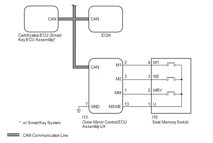
ECM |
Main Body ECU (Driver Side Junction Block Assembly) |
|
CAN |
|
Outer Mirror Control ECU Assembly LH |
Main Body ECU (Driver Side Junction Block Assembly) |
|
CAN |
|
Main Body ECU (Driver Side Junction Block Assembly) |
Position Control ECU and Switch Assembly |
|
CAN |
|
Certification ECU (Smart Key ECU Assembly)* |
Main Body ECU (Driver Side Junction Block Assembly) |
|
CAN |
|
Position Control ECU and Switch Assembly |
Main Body ECU (Driver Side Junction Block Assembly) |
|
CAN |
- *: w/ Smart Key System
 System Description
SYSTEM DESCRIPTION
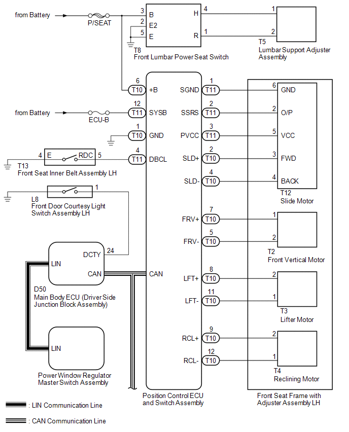
1. FRONT POWER SEAT CONTROL SYSTEM DESCRIPTION
The driver seat is equipped with slide, reclining, lifter, front vertical,
and lumbar support adjustment functions.
T ...
 How To Proceed With Troubleshooting
CAUTION / NOTICE / HINT
HINT:
Use the following procedure to troubleshoot the front power seat control
system (w/ Memory).
*: Use the Techstream.
PROCEDURE
1.
...
Other materials about Toyota Venza:
Problem Symptoms Table
PROBLEM SYMPTOMS TABLE
HINT:
Use the table below to help determine the cause of problem symptoms.
If multiple suspected areas are listed, the potential causes of the symptoms
are listed in order of probability in the "Suspected Area" ...
Washer Motor(for Rear Side)
Components
COMPONENTS
ILLUSTRATION
Removal
REMOVAL
PROCEDURE
1. REMOVE FRONT WHEEL RH
2. REMOVE FRONT FENDER OUTSIDE MOULDING RH
HINT:
Use the same procedure for the RH side and LH side (See page
).
3. REMOVE FRONT FENDER LINER RH
4. DRAI ...
Data List / Active Test
DATA LIST / ACTIVE TEST
1. DATA LIST
HINT:
Using the Techstream to read the Data List allows the values or states of switches,
sensors, actuators and other items to be read without removing any parts. This non-intrusive
inspection can be very useful bec ...

0.1317