Toyota Venza: Rear Wheel House Plate
Components
COMPONENTS
ILLUSTRATION
Installation
INSTALLATION
PROCEDURE
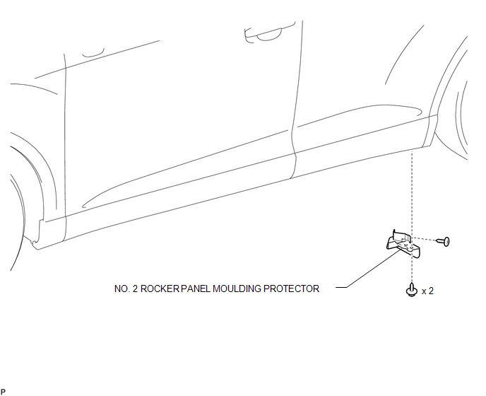
1. INSTALL NO. 2 ROCKER PANEL MOULDING PROTECTOR
|
(a) Install the No. 2 rocker panel moulding protector with the 2 screws <B>. |
|
(b) Install the screw <A>.
Removal
REMOVAL
PROCEDURE
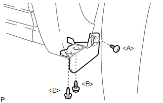
1. REMOVE NO. 2 ROCKER PANEL MOULDING PROTECTOR
|
(a) Remove the screw <A>. |
|
.png)
(b) Remove the 2 screws <B> and remove the No. 2 rocker panel moulding protector.
 Rear Spoiler
Components
COMPONENTS
ILLUSTRATION
Removal
REMOVAL
PROCEDURE
1. REMOVE UPPER BACK WINDOW PANEL TRIM
2. REMOVE REAR SPOILER ASSEMBLY
(a) Disconnect the connector.
...
 Rocker Panel Moulding
Components
COMPONENTS
ILLUSTRATION
Removal
REMOVAL
PROCEDURE
1. REMOVE FRONT FENDER OUTSIDE MOULDING
2. REMOVE NO. 2 ROCKER PANEL MOULDING PROTECTOR
3. REMOVE REAR ROCKER PANEL MOU ...
Other materials about Toyota Venza:
Installing child restraints
Follow the child restraint system manufacturer’s instructions. Firmly secure
child restraints to the rear seats using the LATCH anchors or a seat belt. Attach
the top tether strap when installing a child restraint.
The lap/shoulder belt can be used if y ...
Data List / Active Test
DATA LIST / ACTIVE TEST
1. DATA LIST
HINT:
Using the Techstream to read the Data List allows the values or states of switches,
sensors, actuators and other items to be read without removing any parts. This non-intrusive
inspection can be very useful bec ...
Reverse Shift-linked Function of Power Mirrors does not Operate
SYSTEM DESCRIPTION
On receiving a reverse signal from the park/neutral position switch assembly,
the ECM sends the reverse signal to the main body ECU (driver side junction block
assembly) via CAN communication. When receiving the reverse signal, the main ...

0.1287