Toyota Venza: Removal
REMOVAL
PROCEDURE
1. DISCONNECT CABLE FROM NEGATIVE BATTERY TERMINAL
NOTICE:
When disconnecting the cable, some systems need to be initialized after the cable
is reconnected (See page .gif) ).
).
2. REMOVE NO. 1 ENGINE COVER SUB-ASSEMBLY
3. REMOVE COOL AIR INTAKE DUCT SEAL
4. REMOVE NO. 1 ENGINE UNDER COVER
5. REMOVE NO. 2 ENGINE UNDER COVER
6. DRAIN ENGINE COOLANT
7. REMOVE V-RIBBED BELT
HINT:
See page
8. REMOVE WIRE HARNESS CLAMP BRACKET
9. REMOVE GENERATOR ASSEMBLY
10. REMOVE V-RIBBED BELT TENSIONER ASSEMBLY
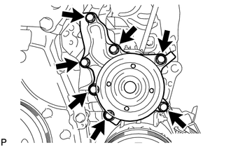
11. REMOVE WATER PUMP ASSEMBLY
|
(a) Remove the 7 bolts, water pump and water pump gasket. |
|
 On-vehicle Inspection
ON-VEHICLE INSPECTION
PROCEDURE
1. INSPECT FOR COOLANT LEAK
HINT:
The sliding surface inside the engine water pump assembly is lubricated
by engine coolant. As some engine coolant is d ...
 Installation
INSTALLATION
PROCEDURE
1. INSTALL WATER PUMP ASSEMBLY
(a) Install a new gasket and the water pump with the 7 bolts.
Torque:
21 N·m {214 kgf·cm, 15 ft·lbf}
...
Other materials about Toyota Venza:
Readiness Monitor Drive Pattern
READINESS MONITOR DRIVE PATTERN
1. PURPOSE OF READINESS TESTS
The On-Board Diagnostic (OBD II) system is designed to monitor the performance
of emission related components, and indicate any detected abnormalities
using DTCs (Diagnostic Trouble ...
System Diagram
SYSTEM DIAGRAM
Communication Table
Sender
Receiver
Signal
Line
Main Body ECU
(Driver Side Junction Block Assembly)
Clearance Warning ECU Assembly
Destination information
...
Steering Lock Position Signal Circuit Malfunction (B2285)
DESCRIPTION
This DTC is stored when serial communication signals and LIN communication signals
in the circuit between the power management control ECU and steering lock actuator
assembly (steering lock ECU) are inconsistent.
DTC No.
...

0.1149