Toyota Venza: Installation
INSTALLATION
CAUTION / NOTICE / HINT
HINT:
- Use the same procedure for the RH side and LH side.
- The procedure listed below is for the LH side.
PROCEDURE
1. INSTALL REAR AXLE CARRIER SUB-ASSEMBLY
|
(a) Temporarily install the rear axle carrier sub-assembly with the 2 bolts and 2 nuts. |
|
.png)
|
(b) Install the rear axle carrier sub-assembly with the 2 bolts and 2 nuts. Torque: 290 N·m {2957 kgf·cm, 214 ft·lbf} NOTICE: When installing the nuts, keep the bolts from rotating. |
|
.png)
2. INSTALL REAR STRUT ROD ASSEMBLY
.gif)
3. INSTALL NO. 3 PARKING BRAKE CABLE ASSEMBLY
4. INSTALL REAR AXLE HUB AND BEARING ASSEMBLY
5. INSTALL REAR SPEED SENSOR WIRE
6. INSTALL REAR DISC
7. INSTALL REAR DISC BRAKE CALIPER ASSEMBLY
8. STABILIZE SUSPENSION
9. FULLY TIGHTEN REAR NO. 1 SUSPENSION ARM ASSEMBLY
|
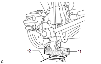
(a) Support the rear axle carrier sub-assembly using a jack and wooden block as shown in the illustration. Text in Illustration
NOTICE: Do not bend the brake dust cover. |
|
|
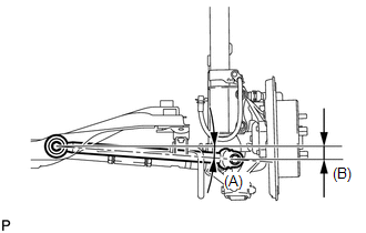
(b) Jack up the rear axle carrier sub-assembly LH to set the rear No. 1 suspension arm assembly LH in the tightening position as shown in the illustration. Standard angle (A): 4°36' (4.6°) Standard length (B): 38.6 mm (1.52 in.) CAUTION: Do not jack up the rear axle carrier sub-assembly LH too high as the vehicle may fall. HINT: If the rear No. 1 suspension arm assembly LH cannot be positioned as shown in the illustration even when the rear axle carrier sub-assembly LH is jacked up, apply additional load to the vehicle such as by having a person sit in the rear seat. |
|
|
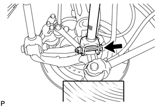
(c) Fully tighten the bolt. Torque: 112 N·m {1141 kgf·cm, 82 ft·lbf} NOTICE:
|
|
10. FULLY TIGHTEN REAR NO. 2 SUSPENSION ARM ASSEMBLY
|
(a) Support the rear axle carrier sub-assembly using a jack and wooden block as shown in the illustration. Text in Illustration
NOTICE: Do not bend the brake dust cover. |
|
|
(b) Jack up the rear axle carrier sub-assembly LH to set the rear No. 2 suspension arm assembly LH in the tightening position as shown in the illustration. Standard angle (A): 4°36' (4.6°) Standard length (B): 39.1 mm (1.54 in.) CAUTION: Do not jack up the rear axle carrier sub-assembly LH too high as the vehicle may fall. HINT: If the rear No. 2 suspension arm assembly LH cannot be positioned as shown in the illustration even when the rear axle carrier sub-assembly LH is jacked up, apply additional load to the vehicle such as by having a person sit in the rear seat. |
|

|
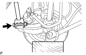
(c) Fully tighten the bolt. Torque: 112 N·m {1141 kgf·cm, 82 ft·lbf} NOTICE:
|
|
11. INSTALL REAR WHEEL
Torque:
103 N·m {1050 kgf·cm, 76 ft·lbf}
12. INSPECT AND ADJUST REAR WHEEL ALIGNMENT
(a) Inspect and adjust the front wheel alignment (See page
).
13. CHECK FOR SPEED SENSOR SIGNAL
(a) Check for the speed sensor signal (See page
).
 Removal
REMOVAL
CAUTION / NOTICE / HINT
HINT:
Use the same procedure for the RH side and LH side.
The procedure listed below is for the LH side.
PROCEDURE
1. REMOVE REAR WHEEL
2. SEPAR ...

Other materials about Toyota Venza:
Emission Control System
Parts Location
PARTS LOCATION
ILLUSTRATION
On-vehicle Inspection
ON-VEHICLE INSPECTION
PROCEDURE
1. INSPECT FUEL CUT-OFF RPM
(a) Increase the engine speed to at least 3500 rpm.
(b) Use a sound scope to check for injector operating soun ...
Disposal
DISPOSAL
CAUTION / NOTICE / HINT
CAUTION:
Before performing pre-disposal deployment of any SRS component, review and closely
follow all applicable environmental and hazardous material regulations. Pre-disposal
deployment may be considered hazardous mate ...
Components
COMPONENTS
ILLUSTRATION
ILLUSTRATION
ILLUSTRATION
ILLUSTRATION
ILLUSTRATION
...

0.1482