Toyota Venza: On-vehicle Inspection
ON-VEHICLE INSPECTION
PROCEDURE
1. INSPECT FOR COOLANT LEAK
HINT:
- The sliding surface inside the engine water pump assembly is lubricated by engine coolant. As some engine coolant is discharged during normal operation, engine coolant residue (solids) may be found on the drain plug or the bottom of the engine water pump assembly. Also, engine coolant may leak if foreign matter enters the engine water pump assembly, however the sealing performance will recover when the foreign matter is pushed out or breaks into fine pieces. In this case, check the area around the engine water pump assembly.
- Before performing this inspection, check that there are no engine coolant leaks from any parts other than the engine water pump assembly. If there are leaks, inspect those areas first.
- Perform this inspection when the engine is cold.
(a) Visually check the engine water pump assembly.
(1) Check that engine coolant is not dripping from the engine water pump assembly.
HINT:
- If engine coolant is dripping, replace the engine water pump assembly.
- If engine coolant is not dripping, perform the following check.
(b) Inspect the area around the engine water pump assembly.
HINT:
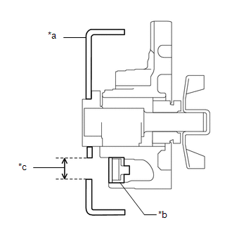
Check for deposits around the drain plug of the engine water pump assembly.
|
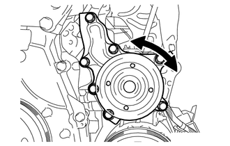
(1) Rotate the crankshaft pulley and align the water pump pulley hole with the drain plug. Text in Illustration
HINT:
|
|
|
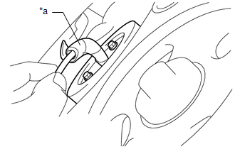
(2) Wrap a thin paper towel around an L-shaped tool such as a hexagon wrench, and insert it into the water pump pulley hole. Text in Illustration
HINT:
|
|
|
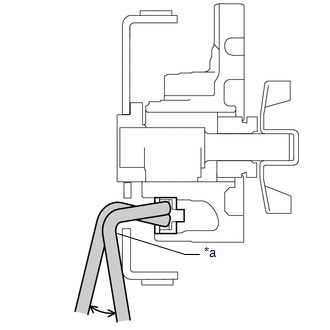
(3) Move the hexagon wrench as shown in the illustration, and press the paper towel against the engine coolant (solid matter) adhered to the drain plug or the edge of the drain plug, and check the condition of the paper towel. Text in Illustration
HINT:
|
|
2. INSPECT WATER PUMP ASSEMBLY
(a) Remove the V-ribbed belt.
See page .gif)
|
(b) Turn the water pump pulley and check that the water pump bearing moves smoothly and quietly. If necessary, replace the engine water pump assembly. |
|
(c) Install the V-ribbed belt.
See page
 Components
COMPONENTS
ILLUSTRATION
ILLUSTRATION
ILLUSTRATION
...
 Removal
REMOVAL
PROCEDURE
1. DISCONNECT CABLE FROM NEGATIVE BATTERY TERMINAL
NOTICE:
When disconnecting the cable, some systems need to be initialized after the cable
is reconnected (See page ).
2. RE ...
Other materials about Toyota Venza:
Power back door switch (vehicles with power back door)
Push the switch to close.
Pressing the switch again while the power back door is closing will cause it
to open again.
However, the reverse operation cannot be performed for the first second after
pressing the switch to close the door.
The back door ca ...
Throttle Actuator Control Throttle Body Range / Performance (P2119)
DESCRIPTION
The electronic throttle control system is composed of the throttle actuator,
throttle position sensor, accelerator pedal position sensor, and ECM. The ECM operates
the throttle actuator to regulate the throttle valve in response to driver inpu ...
Lost Communication with ECM / PCM "A" (U0100-U0142,U0155)
DESCRIPTION
These DTCs are stored when the clearance warning ECU assembly cannot receive
and recognize several signals via the CAN communication system.
DTC No.
DTC Detection Condition
Trouble Area
U0100
...

0.1438