Toyota Venza: Installation
INSTALLATION
CAUTION / NOTICE / HINT
HINT:
- Use the same procedure for the RH side and LH side.
- The procedure listed below is for the LH side.
PROCEDURE
1. INSTALL REAR STRUT ROD ASSEMBLY (for 2WD)
|
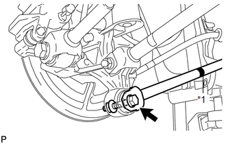
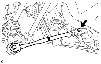
(a) Temporarily install the rear strut rod assembly to the rear axle carrier sub-assembly with the bolt and the nut. Text in Illustration
NOTICE:
|
|
|
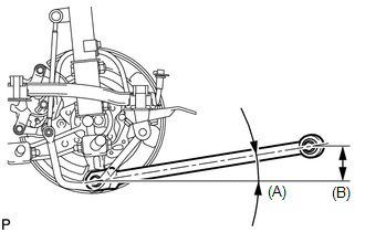
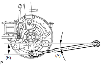
(b) Set the rear strut rod assembly in the tightening position shown in the illustration. Standard angle (A): 9°54' (9.9°) Standard length (B): 83.9 mm (3.30 in.) |
|
|
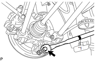
(c) Fully tighten the bolt in the tightening position. Torque: 80 N·m {816 kgf·cm, 59 ft·lbf} |
|
|
(d) Temporarily install the rear strut rod assembly to the body with the bolt and the nut. |
|
|
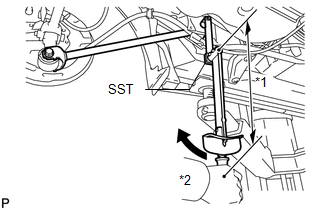
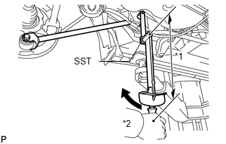
(e) Using SST and a socket wrench (17 mm), fully tighten the bolt in the rebound position. Text in Illustration
SST: 09961-00950 Torque: Specified Tightening Torque : 80 N·m {816 kgf·cm, 59 ft·lbf} NOTICE:
HINT:
|
|
.gif) ).
). 
2. INSTALL REAR STRUT ROD ASSEMBLY (for AWD)
|
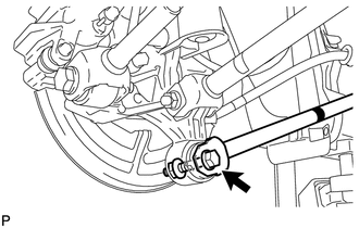
(a) Temporarily install the rear strut rod assembly to the rear axle carrier sub-assembly with the bolt and the nut. Text in Illustration
NOTICE:
|
|
|
(b) Set the rear strut rod assembly in the tightening position shown in the illustration. Standard angle (A): 9°3' (9.04°) Standard length (B): 78.3 mm (3.08 in.) |
|
|
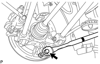
(c) Fully tighten the bolt in the tightening position. Torque: 80 N·m {816 kgf·cm, 59 ft·lbf} |
|
|
(d) Temporarily install the rear strut rod assembly to the body with the bolt and the nut. |
|
|
(e) Using SST and a socket wrench (17 mm), fully tighten the bolt in the rebound position. Text in Illustration
SST: 09961-00950 Torque: Specified Tightening Torque : 80 N·m {816 kgf·cm, 59 ft·lbf} NOTICE:
HINT:
|
|
3. INSTALL NO. 3 PARKING BRAKE CABLE ASSEMBLY
|
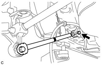
(a) Install the No. 3 parking brake cable assembly with the bolt. Torque: 6.0 N·m {61 kgf·cm, 53 in·lbf} NOTICE: Do not twist the No. 3 parking brake cable assembly when installing it. |
|
.png)
4. INSTALL REAR WHEEL
Torque:
103 N·m {1050 kgf·cm, 76 ft·lbf}
5. STABILIZE SUSPENSION
(a) Lower the vehicle to the ground.
(b) Bounce the vehicle up and down at the corners to stabilize the rear suspension.
 Removal
REMOVAL
CAUTION / NOTICE / HINT
HINT:
Use the same procedure for the RH side and LH side.
The procedure listed below is for the LH side.
PROCEDURE
1. REMOVE REAR WHEEL
2. SEPAR ...

Other materials about Toyota Venza:
Removal
REMOVAL
PROCEDURE
1. DISCONNECT CABLE FROM NEGATIVE BATTERY TERMINAL
NOTICE:
When disconnecting the cable, some systems need to be initialized after the cable
is reconnected (See page ).
2. REMOVE COOL AIR INTAKE DUCT SEAL
3. REMOVE NO. 1 ENGINE CO ...
Open / Short in Steering Lock ECU (B2781)
DESCRIPTION
If the steering lock ECU (steering lock actuator assembly) determines that there
is a malfunction inside the ECU, it outputs this DTC. Diagnostic communication between
the steering lock ECU (steering lock actuator assembly) and the Techstream ...
Front Occupant Classification Sensor RH Circuit Malfunction (B1781)
DESCRIPTION
The front occupant classification sensor RH circuit consists of the occupant
classification ECU and front occupant classification sensor RH.
DTC B1781 is recorded when a malfunction is detected in the front occupant classification
sensor RH c ...

0.125