Toyota Venza: Installation
INSTALLATION
PROCEDURE
1. INSTALL CENTER AIRBAG SENSOR ASSEMBLY
(a) Check that the ignition switch is off.
(b) Check that the cable is disconnected from the negative (-) battery terminal.
CAUTION:
Wait at least 90 seconds after disconnecting the cable from the negative (-) battery terminal to disable the SRS system.
|
(c) Install the center airbag sensor assembly with the 3 bolts. Text in Illustration
Torque: 18 N·m {178 kgf·cm, 13 ft·lbf} NOTICE:
|
|
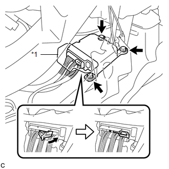
(d) Connect the connector to the center airbag sensor assembly as shown in the illustration.
NOTICE:
When connecting the airbag connector, take care not to damage the airbag wire harness.
(e) Check that the waterproof sheet is properly set.
(f) Check that there is no looseness in the installation parts of the center airbag sensor assembly.
2. INSTALL CONSOLE BOX SUB-ASSEMBLY
.gif)
3. INSTALL SHIFT LEVER KNOB SUB-ASSEMBLY
4. INSTALL CONSOLE BOX ASSEMBLY
5. INSTALL NO. 2 CONSOLE BOX CARPET
6. INSTALL LOWER INSTRUMENT PANEL SUB-ASSEMBLY
7. INSTALL NO. 2 INSTRUMENT PANEL UNDER COVER SUB-ASSEMBLY
8. INSTALL COWL SIDE TRIM SUB-ASSEMBLY RH
9. INSTALL FRONT DOOR SCUFF PLATE RH
10. INSTALL AIR CONDITIONER CONTROL ASSEMBLY
11. INSTALL UPPER CONSOLE PANEL SUB-ASSEMBLY (w/o Seat Heater System)
12. INSTALL UPPER CONSOLE PANEL SUB-ASSEMBLY (w/ Seat Heater System)
13. INSTALL LOWER NO. 1 INSTRUMENT PANEL FINISH PANEL
14. INSTALL COWL SIDE TRIM SUB-ASSEMBLY LH
15. INSTALL FRONT DOOR SCUFF PLATE LH
16. CONNECT CABLE TO NEGATIVE BATTERY TERMINAL
NOTICE:
When disconnecting the cable, some systems need to be initialized after the cable
is reconnected (See page ).
17. PERFORM DIAGNOSTIC SYSTEM CHECK
(a) Perform a diagnostic system check (See page
).
18. INSPECT SRS WARNING LIGHT
(a) Inspect the SRS warning light (See page
).
 Removal
REMOVAL
PROCEDURE
1. PRECAUTION
CAUTION:
Be sure to read Precaution thoroughly before servicing (See page
).
2. DISCONNECT CABLE FROM NEGATIVE BATTERY TERMINAL
CAUTION:
Wait at least 90 secon ...

Other materials about Toyota Venza:
Short in Side Squib LH Circuit (B1825/56-B1828/56)
DESCRIPTION
The side squib LH circuit consists of the center airbag sensor assembly and front
seat side airbag assembly LH.
The center airbag sensor assembly uses this circuit to deploy the airbag when
deployment conditions are met.
These DTCs are store ...
Noise Occurs or Sound Skips when Portable Player Plays
CAUTION / NOTICE / HINT
HINT:
Perform this check with the portable player volume set at an appropriate
level.
Make sure that there are no obstructions between the portable player
and the radio and display receiver assembly that may block ...
Installation
INSTALLATION
PROCEDURE
1. INSTALL NO. 2 BACK WINDOW GLASS SPACER
(a) Apply Primer G to the installation part of the No. 2 back window glass spacer.
HINT:
If primer is applied to an area that is not specified, wipe off the primer with
a non-residue solve ...

0.1494