Toyota Venza: Removal
REMOVAL
PROCEDURE
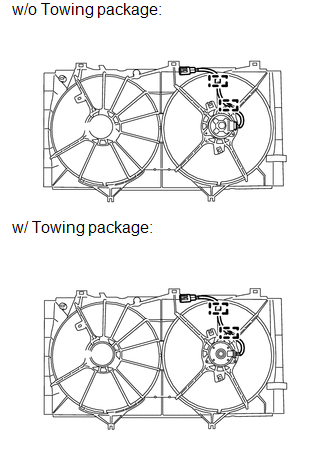
1. REMOVE RADIATOR ASSEMBLY AND FAN ASSEMBLY WITH MOTOR
HINT:
See page .gif)
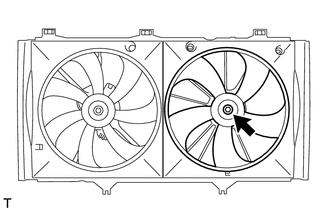
2. REMOVE FAN
|
(a) Remove the nut and fan. |
|
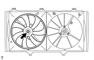
3. REMOVE NO. 2 FAN
|
(a) Remove the nut and No. 2 fan. |
|
4. REMOVE COOLING FAN MOTOR INSULATOR
|
(a) Remove the 2 bolts and cooling fan motor insulator. |
|
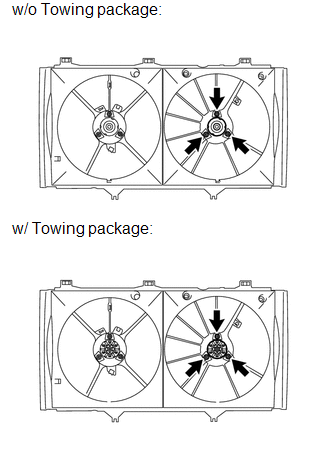
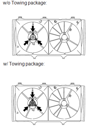
5. REMOVE COOLING FAN MOTOR
|
(a) Remove the 3 screws and cooling fan motor. |
|
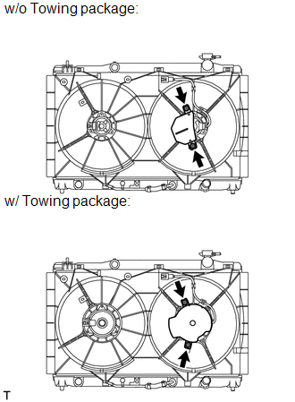
6. REMOVE NO. 2 COOLING FAN MOTOR
|
(a) Disconnect the No. 2 cooling fan motor connector and 2 clamps. |
|
|
(b) Remove the 3 screws and No. 2 cooling fan motor. |
|
 On-vehicle Inspection
ON-VEHICLE INSPECTION
PROCEDURE
1. INSPECT COOLING FAN MOTOR
(a) Check that the motor operates smoothly when the battery is connected
to the cooling fan motor connector.
Text in I ...
 Installation
INSTALLATION
PROCEDURE
1. INSTALL NO. 2 COOLING FAN MOTOR
(a) Install the No. 2 cooling fan motor with the 3 screws.
Torque:
w/o Towing package :
2.6 N·m {26 kgf·cm, 23 in· ...
Other materials about Toyota Venza:
Installation
INSTALLATION
PROCEDURE
1. INSTALL WINDSHIELD WIPER SWITCH ASSEMBLY
(a) Engage the claw to install the windshield wiper switch assembly as
shown in the illustration.
(b) Connect the 2 connectors. ...
Short in Front Passenger Side Squib 2nd Step Circuit (B1815/54-B1818/54)
DESCRIPTION
The front passenger side squib 2nd step circuit consists of the center airbag
sensor assembly and front passenger airbag assembly.
The center airbag sensor assembly uses this circuit to deploy the airbag when
deployment conditions are met.
T ...
Terminals Of Ecu
TERMINALS OF ECU
1. CLEARANCE WARNING ECU ASSEMBLY
(a) Disconnect the D79 clearance warning ECU assembly connector.
(b) Measure the voltage and resistance according to the value(s) in the table
below.
Terminal No. (Symbol)
Wiring ...

0.1631