Toyota Venza: Removal
REMOVAL
PROCEDURE
1. REMOVE AUTOMATIC TRANSAXLE ASSEMBLY
HINT:
See the steps from "Remove Engine Assembly with transaxle" through "Remove Automatic
Transaxle Assembly" (See page .gif) ).
).
2. REMOVE AUTOMATIC TRANSAXLE OIL PAN SUB-ASSEMBLY
3. REMOVE VALVE BODY OIL STRAINER ASSEMBLY
4. REMOVE ATF TEMPERATURE SENSOR ASSEMBLY
|
(a) Disconnect the ATF temperature sensor assembly connector. |
|
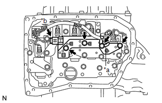
(b) Remove the 4 bolts, ATF temperature sensor assembly and clamp from the transmission valve body assembly.
Text in Illustration|
*a |
Clamp |
|
*b |
ATF Temperature Sensor Assembly Connector |
|
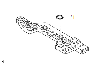
(c) Remove the O-ring from the ATF temperature sensor assembly. Text in Illustration
|
|
 Components
COMPONENTS
ILLUSTRATION
...
 Inspection
INSPECTION
PROCEDURE
1. INSPECT ATF TEMPERATURE SENSOR ASSEMBLY
(a) Measure the resistance according to the value(s) in the table below.
Standard Resistance:
Test ...
Other materials about Toyota Venza:
Removal
REMOVAL
CAUTION / NOTICE / HINT
NOTICE:
w/Camera mirror:The timing of the change between high beams and low beams differs
depending on the light transmission rate of the glass. For this reason, when replacing
the windshield, replace it with an original ...
Intake System
Parts Location
PARTS LOCATION
ILLUSTRATION
System Diagram
SYSTEM DIAGRAM
On-vehicle Inspection
ON-VEHICLE INSPECTION
PROCEDURE
1. INSPECT INTAKE SYSTEM
HINT:
Perform "Inspection After Repair" after repairing vacuum leaks in the ...
Precaution
PRECAUTION
1. EXPRESSIONS OF IGNITION SWITCH
The type of ignition switch used on this model differs according to the specifications
of the vehicle.
The expressions listed in the table below are used in this section.
Expression
Switc ...

0.1411