Toyota Venza: Inspection
INSPECTION
PROCEDURE
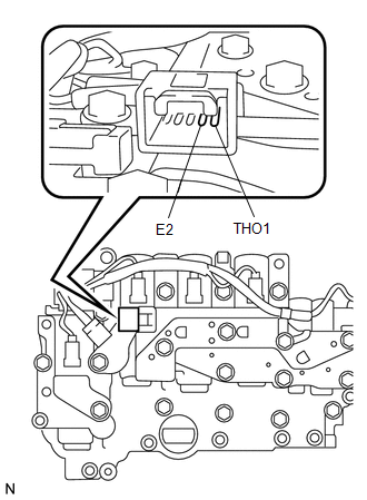
1. INSPECT ATF TEMPERATURE SENSOR ASSEMBLY
|
(a) Measure the resistance according to the value(s) in the table below. Standard Resistance:
If the resistance is out of the specified range with the ATF temperature shown in the preceding table, replace the ATF temperature sensor assembly. Otherwise, the driveability of the vehicle may decrease. |
|
 Removal
REMOVAL
PROCEDURE
1. REMOVE AUTOMATIC TRANSAXLE ASSEMBLY
HINT:
See the steps from "Remove Engine Assembly with transaxle" through "Remove Automatic
Transaxle Assembly" (See p ...
 Installation
INSTALLATION
PROCEDURE
1. INSTALL ATF TEMPERATURE SENSOR ASSEMBLY
(a) Coat a new O-ring with ATF and install it to the ATF temperature
sensor assembly.
Text in Illustration
...
Other materials about Toyota Venza:
Solar Sensor
Components
COMPONENTS
ILLUSTRATION
On-vehicle Inspection
ON-VEHICLE INSPECTION
PROCEDURE
1. INSPECT SOLAR SENSOR
(a) Disconnect the solar sensor connector.
(b) Measure the voltage accordin ...
Removal
REMOVAL
CAUTION / NOTICE / HINT
NOTICE:
Release the vacuum from the booster by depressing the brake pedal several times.
Then remove the brake master cylinder from the brake booster.
PROCEDURE
1. REMOVE FRONT WIPER ARM HEAD CAP
2. REMOVE FRONT WIPER AR ...
Lost Communication with ECM / PCM (U0100)
DESCRIPTION
DTC No.
DTC Detection Condition
Trouble Area
U0100
No communication from the ECM continues.
ECM main wire or connector
Power source circuit of ECM
ECM
...

0.172