Toyota Venza: Removal
REMOVAL
CAUTION / NOTICE / HINT
NOTICE:
Release the vacuum from the booster by depressing the brake pedal several times. Then remove the brake master cylinder from the brake booster.
PROCEDURE
1. DRAIN BRAKE FLUID
NOTICE:
If brake fluid leaks onto any painted surface, immediately wash it off.
2. REMOVE AIR CLEANER CAP SUB-ASSEMBLY (for 1AR-FE)
.gif)
3. REMOVE AIR CLEANER CAP SUB-ASSEMBLY (for 2GR-FE)
4. REMOVE AIR CLEANER FILTER ELEMENT SUB-ASSEMBLY
5. REMOVE BRAKE MASTER CYLINDER SUB-ASSEMBLY
|
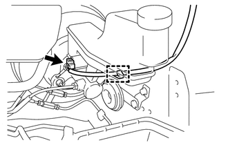
(a) Disconnect the connector and disengage the clamp. |
|
|
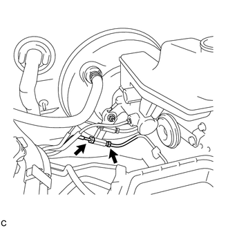
(b) Using a union nut wrench, disconnect the 2 brake lines from the front brake tube way. NOTICE:
|
|
|
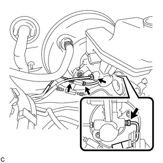
(c) Using a union nut wrench, disconnect the 2 brake lines and remove the No. 1 front brake tube from the brake master cylinder sub-assembly. NOTICE:
|
|
|
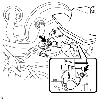
(d) Remove the 2 nuts, front brake tube way and brake master cylinder sub-assembly from the brake booster assembly. NOTICE:
|
|
(e) Remove the O-ring from the brake master cylinder sub-assembly.
 Disassembly
DISASSEMBLY
PROCEDURE
1. REMOVE BRAKE MASTER CYLINDER RESERVOIR ASSEMBLY
(a) Mount the brake master cylinder sub-assembly in a vise.
NOTICE:
Place aluminum plates on the vise to prevent damage to ...
 Installation
INSTALLATION
PROCEDURE
1. INSTALL BRAKE MASTER CYLINDER SUB-ASSEMBLY
NOTICE:
When install a new brake master cylinder sub-assembly, remove the protectors
from the piston and outlet ports.
(a) I ...
Other materials about Toyota Venza:
Headlight Solenoid Circuit
DESCRIPTION
for HID Headlight:
When the main body ECU receives a high beam turn on signal, the main
body ECU activates the bi-function by controlling the BI-XENON relay. The
bi-function increases the upper illumination area of the discharge ...
Installation
INSTALLATION
CAUTION / NOTICE / HINT
HINT:
Perform "Inspection After Repair" after replacing the camshaft, No. 2 camshaft,
camshaft timing gear assembly or camshaft timing exhaust gear assembly (See page
).
PROCEDURE
1. INSTALL NO. 2 CAMSHAF ...
SFR Solenoid Circuit (C0226/21,C0236/22,C0246/23,C0256/24,C1225/25-C1228/28)
DESCRIPTION
These solenoids turn on when signals are received from the skid control ECU and
they control the pressure acting on the wheel cylinders to control the braking force.
DTC Code
DTC Detection Condition
Trouble Area ...

0.1481