Toyota Venza: Installation
INSTALLATION
PROCEDURE
1. INSTALL BRAKE MASTER CYLINDER SUB-ASSEMBLY
NOTICE:
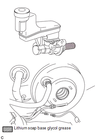
When install a new brake master cylinder sub-assembly, remove the protectors from the piston and outlet ports.
(a) Install a new O-ring to the brake master cylinder sub-assembly.
|
(b) Apply a light layer of lithium soap base glycol grease to the entire circumference of the brake master cylinder sub-assembly and inner surface of the brake booster assembly as shown in the illustration. |
|
|
(c) Install the brake master cylinder sub-assembly and front brake tube way with the 2 nuts. Torque: 13 N·m {130 kgf·cm, 9 ft·lbf} NOTICE:
|
|
.png)
|
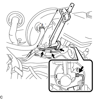
(d) Using a union nut wrench, connect the 2 brake lines and install the No. 1 front brake tube to the brake master cylinder sub-assembly. Text in Illustration
Torque: Specified Tightening Torque : 20 N·m {199 kgf·cm, 14 ft·lbf} NOTICE:
HINT:
|
|
|
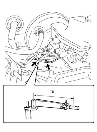
(e) Using a union nut wrench, connect the 2 brake lines to the front brake tube way. Text in Illustration
Torque: Specified Tightening Torque : 15 N·m {155 kgf·cm, 11 ft·lbf} NOTICE:
HINT:
|
|
|
(f) Connect the connector and engage the clamp. |
|
.png)
2. FILL RESERVOIR WITH BRAKE FLUID
.gif)
3. BLEED BRAKE MASTER CYLINDER
4. BLEED BRAKE LINE
5. INSPECT FOR BRAKE FLUID LEAK
6. INSPECT FLUID LEVEL IN RESERVOIR
7. INSTALL AIR CLEANER FILTER ELEMENT SUB-ASSEMBLY
8. INSTALL AIR CLEANER CAP SUB-ASSEMBLY (for 1AR-FE)
9. INSTALL AIR CLEANER CAP SUB-ASSEMBLY (for 2GR-FE)
 Removal
REMOVAL
CAUTION / NOTICE / HINT
NOTICE:
Release the vacuum from the booster by depressing the brake pedal several times.
Then remove the brake master cylinder from the brake booster.
PROCEDURE
...
 Reassembly
REASSEMBLY
PROCEDURE
1. INSTALL BRAKE MASTER CYLINDER RESERVOIR ASSEMBLY
(a) Apply a light layer of lithium soap base glycol grease to the entire circumference
of 2 new brake master cylinder rese ...
Other materials about Toyota Venza:
ACC Monitor Malfunction (B2274)
DESCRIPTION
This DTC is stored when there is a problem in the ACC output circuit. The ACC
circuit is the circuit that goes from inside the power management control ECU to
the ACC relay.
DTC No.
DTC Detection Condition
Tro ...
Disassembly
DISASSEMBLY
PROCEDURE
1. REMOVE NO. 1 AIR DUCT SUB-ASSEMBLY
(a) Disengage the 4 claws and remove the No. 1 air duct sub-assembly.
2. REMOVE AIR FILTER COVER PLATE
(a) Disengage the 2 cla ...
Problem Symptoms Table
PROBLEM SYMPTOMS TABLE
HINT:
Use the table below to help determine the cause of problem symptoms.
If multiple suspected areas are listed, the potential causes of the symptoms
are listed in order of probability in the "Suspected Area" ...

0.1768