Toyota Venza: Removal
REMOVAL
PROCEDURE
1. REMOVE YAW RATE AND ACCELERATION SENSOR
HINT:
Refer to the instructions for Removal of the yaw rate and acceleration sensor
(See page .gif) ).
).
2. REMOVE REAR NO. 2 AIR DUCT
3. REMOVE REAR NO. 1 AIR DUCT
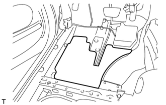
4. REMOVE FRONT NO. 2 FLOOR SILENCER
|
(a) Remove the front No. 2 floor silencer. |
|
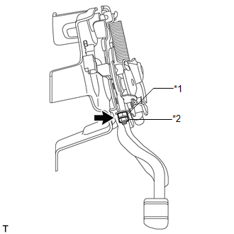
5. LOOSEN PARKING BRAKE
|
(a) Remove the lock nut and No. 1 wire adjusting nut to completely loosen the parking brake. Text in Illustration
|
|
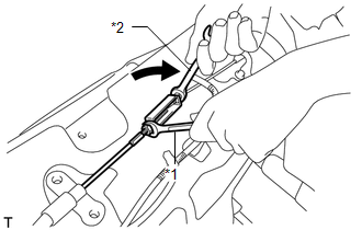
6. DISCONNECT NO. 4 PARKING BRAKE CABLE ASSEMBLY
|
(a) Holding the lock nut of the No. 1 parking brake cable assembly, loosen the turnbuckle of the No. 4 parking brake cable assembly to disconnect the No. 4 parking brake cable assembly from the No. 1 parking brake cable assembly. Text in Illustration
|
|
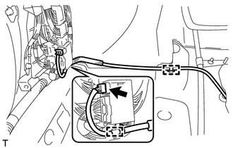
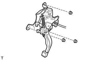
7. REMOVE PARKING BRAKE PEDAL ASSEMBLY
|
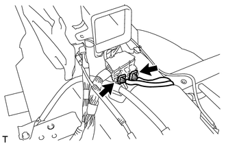
(a) Disconnect the heated oxygen sensor connector and disengage the 2 clamps (for 2GR-FE). |
|
|
(b) Disconnect the 2 connectors. |
|
|
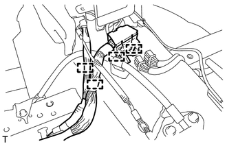
(c) Disengage the 4 clamps and separate the wire harness. |
|
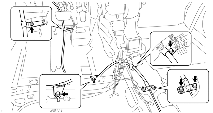
(d) Remove the nut and 4 bolts, and separate the No. 1 parking brake cable assembly from the body.
|
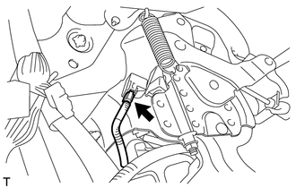
(e) Disconnect the parking brake switch connector. |
|
|
(f) Remove the 3 nuts and parking brake pedal assembly. |
|
 Components
COMPONENTS
ILLUSTRATION
ILLUSTRATION
ILLUSTRATION
ILLUSTRATION
...
 Disassembly
DISASSEMBLY
PROCEDURE
1. REMOVE NO. 1 PARKING BRAKE CABLE ASSEMBLY
2. REMOVE PARKING BRAKE SWITCH ASSEMBLY
3. REMOVE PARKING PEDAL PAD
(a) Remove the parking pedal pad from the parking brak ...
Other materials about Toyota Venza:
Installation
INSTALLATION
PROCEDURE
1. INSTALL FRONT SUSPENSION MEMBER BODY MOUNTING REAR CUSHION LH
(a) Temporarily install a new front suspension member body mounting rear
cushion LH while confirming the installation direction.
NOTICE:
Position th ...
System Diagram
SYSTEM DIAGRAM
Communication Table
Transmitting ECU
Receiving ECU
Signal
Communication Method
Air Conditioning Control Assembly
Air Conditioning Amplifier Assembly
Rear windo ...
General Information
GENERAL INFORMATION
A large number of ECU controlled systems are used in this vehicle. In
general, ECU controlled systems are considered to be very intricate, requiring
a high level of technical knowledge to troubleshoot. However, most problem ...

0.1508