Toyota Venza: Removal
REMOVAL
PROCEDURE
1. REMOVE REAR SEAT HEADREST ASSEMBLY
.gif)
2. REMOVE REAR SEAT INNER TRACK BRACKET COVER
3. REMOVE REAR SEAT OUTER TRACK BRACKET COVER
4. DISCONNECT REAR SEAT NO. 2 RECLINING CONTROL CABLE SUB-ASSEMBLY
5. REMOVE REAR SEAT ASSEMBLY LH
6. REMOVE SEAT ADJUSTER COVER CAP LH
7. REMOVE REAR SEAT RECLINING RELEASE LEVER LH
8. REMOVE REAR SEAT RECLINING COVER LH
9. REMOVE REAR SEAT INNER RECLINING COVER LH
10. REMOVE REAR SEAT CUSHION COVER WITH PAD
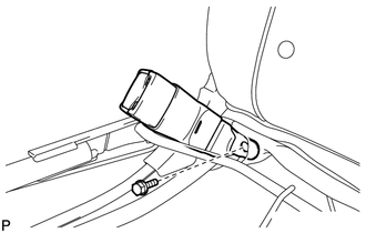
11. REMOVE REAR SEAT INNER BELT ASSEMBLY LH
|
(a) Remove the bolt and the rear seat inner belt assembly LH. |
|
 Components
COMPONENTS
ILLUSTRATION
ILLUSTRATION
...
 Installation
INSTALLATION
PROCEDURE
1. INSTALL REAR SEAT INNER BELT ASSEMBLY LH
(a) Install the rear seat inner belt assembly LH with the bolt.
Text in Illustration
*1
...
Other materials about Toyota Venza:
Trailer towing tips
Your vehicle will handle differently when towing a trailer. Help to avoid an
accident, death or serious injury, keep the following in mind when towing:
• Speed limits for towing a trailer vary by state or province. Do not exceed
the posted towing speed ...
Customize Parameters
CUSTOMIZE PARAMETERS
1. INTUITIVE PARKING ASSIST SYSTEM (See page
)
2. POWER DOOR LOCK CONTROL SYSTEM (See page
)
3. WIRELESS DOOR LOCK CONTROL SYSTEM (w/ Smart Key System) (See page
)
4. WIRELESS DOOR LOCK CONTROL SYSTEM (w/o Smart Key System) (Se ...
HD Radio Tuner Malfunction (B1551,B15A0,B15AD,B15B0,B15B3,B15B4,B15B7)
DESCRIPTION
These DTCs are stored when a malfunction occurs in the navigation receiver assembly.
DTC No.
DTC Detection Condition
Trouble Area
B1551
When any of the following conditions is met:
...

0.1653