
Toyota Venza: Inspection
INSPECTION
PROCEDURE
1. INSPECT REAR NO. 3 SPEAKER ASSEMBLY (for 13 Speakers)
(a) With the speaker installed, check that there is no looseness or other abnormalities.
(b) Check that there is no foreign matter in the speaker, no tears on the speaker cone or other abnormalities.
|
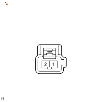
(c) Measure the resistance of the speaker. Standard Resistance:
If the result is not as specified, replace the speaker. Text in Illustration
|
|
 Removal
REMOVAL
PROCEDURE
1. REMOVE REAR DOOR SCUFF PLATE LH
2. REMOVE REAR DOOR OPENING TRIM WEATHERSTRIP LH
3. REMOVE TONNEAU COVER ASSEMBLY (w/ Tonneau Cover)
4. REMOVE DECK BOARD ASSEMBLY
...
 Installation
INSTALLATION
PROCEDURE
1. INSTALL REAR NO. 3 SPEAKER ASSEMBLY
(a) Install the rear No. 3 speaker assembly with the 2 bolts.
(b) Engage the ...
Other materials about Toyota Venza:
Fail-safe Chart
FAIL-SAFE CHART
Engine Coolant Temperature Gauge
Condition
Response
Recovery
Engine coolant temperature data is interrupted for 3 seconds.
The gauge needle indicates below C.
Engine cool ...
Operation Check
OPERATION CHECK
1. CHECK FUNCTION
(a) Check that the key reminder warning buzzer sounds.
(1) With the driver side door closed, insert the key into the ignition key cylinder
and then make sure that the key is in LOCK or ACC.
(2) Check that the buzzer soun ...
Headlight switch
The headlights can be operated manually or automatically.
Turning the end of the lever turns on the lights as follows.
Type A
The daytime running lights turn
on.
The headlights, parking lights, daytime running lights and so on turn on and
off auto ...

0.1215