Toyota Venza: Components
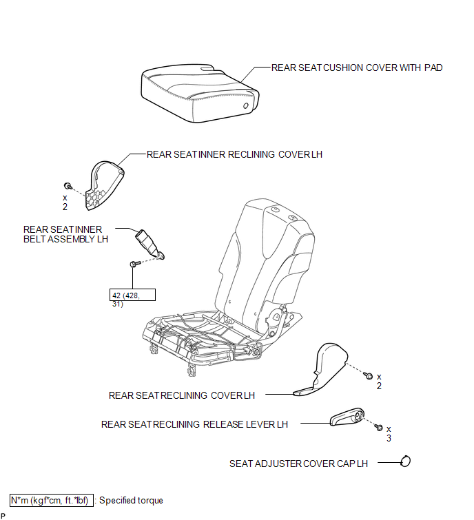
COMPONENTS
ILLUSTRATION
.png)
ILLUSTRATION

 Removal
REMOVAL
PROCEDURE
1. REMOVE REAR SEAT HEADREST ASSEMBLY
2. REMOVE REAR SEAT INNER TRACK BRACKET COVER
3. REMOVE REAR SEAT OUTER TRACK BRACKET COVER
4. DISCONNECT REAR SEAT NO. 2 RECLININ ...
Other materials about Toyota Venza:
Installation
INSTALLATION
CAUTION / NOTICE / HINT
HINT:
Use the same procedure for the RH side and LH side.
The procedure listed below is for the LH side.
PROCEDURE
1. INSTALL REAR STRUT ROD ASSEMBLY (for 2WD)
(a) Temporarily install the ...
Door Control Switch
Components
COMPONENTS
ILLUSTRATION
Inspection
INSPECTION
PROCEDURE
1. INSPECT DOOR CONTROL SWITCH ASSEMBLY
(a) Measure the resistance according to the value(s) in the table below.
Standard Resistance:
Tester Conn ...
Power outlets
The power outlets can be used for 12V accessories that run on less than 10A.
►Console box
►Front passenger’s side instrument panel
►Luggage compartment
- The power outlets can be used when
►Vehicles with smart key sys ...

0.1694