Toyota Venza: Removal
REMOVAL
PROCEDURE
1. REMOVE FRONT SEAT HEADREST ASSEMBLY
2. REMOVE FRONT SEAT REAR OUTER TRACK COVER
.gif)
3. REMOVE FRONT SEAT REAR INNER TRACK COVER
4. REMOVE FRONT SEAT ASSEMBLY
5. REMOVE RECLINING POWER SEAT SWITCH KNOB
6. REMOVE SLIDE AND VERTICAL POWER SEAT SWITCH KNOB
7. REMOVE FRONT SEAT CUSHION SHIELD ASSEMBLY
8. REMOVE FRONT INNER SEAT CUSHION SHIELD
9. REMOVE POWER SEAT SWITCH
10. REMOVE FRONT SEAT INNER BELT ASSEMBLY
11. REMOVE SEPARATE TYPE FRONT SEAT CUSHION COVER WITH PAD
12. REMOVE FRONT SEATBACK BOARD SUB-ASSEMBLY
13. REMOVE SEPARATE TYPE FRONT SEATBACK COVER WITH PAD
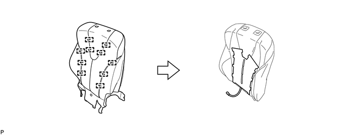
14. REMOVE SEPARATE TYPE FRONT SEATBACK COVER
(a) Remove the 10 hog rings and the separate type front seatback cover.
|
(b) Cut off the 12 tack pins that fasten the seat heater, and then remove the separate type front seatback heater from the front separate type seatback cover. |
|
.png)
 Components
COMPONENTS
ILLUSTRATION
ILLUSTRATION
ILLUSTRATION
...
 Inspection
INSPECTION
PROCEDURE
1. INSPECT FRONT SEATBACK HEATER LH
(a) Apply battery voltage and check the seatback heater.
OK:
Measurement Connection
Cond ...
Other materials about Toyota Venza:
Removal
REMOVAL
PROCEDURE
1. REMOVE REAR SEAT HEADREST ASSEMBLY
2. REMOVE REAR SEAT INNER TRACK BRACKET COVER
3. REMOVE REAR SEAT OUTER TRACK BRACKET COVER
4. DISCONNECT REAR SEAT NO. 2 RECLINING CONTROL CABLE SUB-ASSEMBLY
5. REMOVE REAR SEAT ASSEMBL ...
Precaution
PRECAUTION
1. PRECAUTION FOR DISCONNECTING CABLE FROM NEGATIVE BATTERY TERMINAL
NOTICE:
When disconnecting the cable from the negative (-) battery terminal, initialize
the following system after the terminal is reconnected:
System Name
...
Afs Ecu
Components
COMPONENTS
ILLUSTRATION
Installation
INSTALLATION
PROCEDURE
1. INSTALL AFS ECU
(a) Engage the guide.
(b) Install the AFS ECU with the bolt.
(c) Connect the connector.
2. INSTA ...

0.1558