Toyota Venza: System Diagram
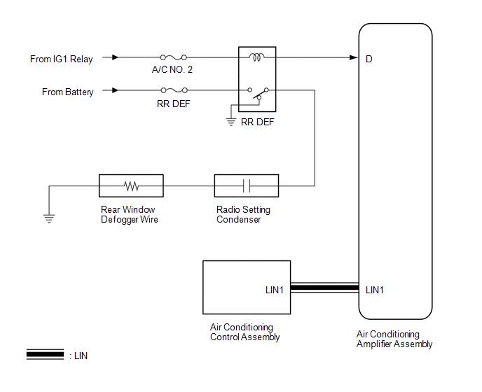
SYSTEM DIAGRAM
 Communication Table
|
Transmitting ECU |
Receiving ECU |
Signal |
Communication Method |
|---|---|---|---|
|
Air Conditioning Control Assembly |
Air Conditioning Amplifier Assembly |
Rear window defogger switch signal |
LIN |
 System Description
SYSTEM DESCRIPTION
1. GENERAL
The rear window defogger wires are attached to the inside of the rear window
and defog the window surface quickly by pressing the rear window defogger switch
on the ...
 How To Proceed With Troubleshooting
CAUTION / NOTICE / HINT
HINT:
Use the following procedure to troubleshoot the window defogger system.
*: Use the Techstream.
PROCEDURE
1.
VEHICLE BROUGH ...
Other materials about Toyota Venza:
ABS Control System Malfunction (43)
DESCRIPTION
This DTC is output when the VSC system detects a malfunction in the ABS control
system.
DTC Code
DTC Detection Condition
Trouble Area
43
Malfunction in the ABS control system.
...
Replacement
REPLACEMENT
PROCEDURE
1. REMOVE CENTER EXHAUST PIPE ASSEMBLY
(a) Remove the center exhaust pipe assembly.
HINT:
Refer to the instructions for Removal of the exhaust pipe (See page
for 2GR-FE,
for 1AR-FE).
2. REMOVE PROPELLER WITH CENTER BEARING SHAF ...
Rear Wheel House Plate
Components
COMPONENTS
ILLUSTRATION
Installation
INSTALLATION
PROCEDURE
1. INSTALL NO. 2 ROCKER PANEL MOULDING PROTECTOR
(a) Install the No. 2 rocker panel moulding protector with the 2 screws
<B>.
...

0.1837