Toyota Venza: Components
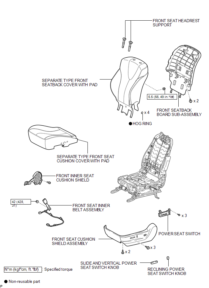
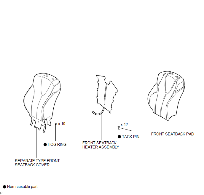
COMPONENTS
ILLUSTRATION
.png)
ILLUSTRATION
ILLUSTRATION

 Removal
REMOVAL
PROCEDURE
1. REMOVE FRONT SEAT HEADREST ASSEMBLY
2. REMOVE FRONT SEAT REAR OUTER TRACK COVER
3. REMOVE FRONT SEAT REAR INNER TRACK COVER
4. REMOVE FRONT SEAT ASSEMBLY
5. REMOVE ...
Other materials about Toyota Venza:
Occupant Classification Ecu
Components
COMPONENTS
ILLUSTRATION
ILLUSTRATION
On-vehicle Inspection
ON-VEHICLE INSPECTION
CAUTION / NOTICE / HINT
CAUTION:
Be sure to follow the correct removal and installation procedures of the occupant
classification ECU.
PROCEDURE
1. ...
Fail-safe Chart
FAIL-SAFE CHART
If a problem occurs in the power steering system, the power steering assist will
be stopped or the amount of power assist will be decreased to protect the system.
Power Steering System
Malfunction
Fail-safe Operation
...
Back Door Courtesy Switch
Components
COMPONENTS
ILLUSTRATION
Removal
REMOVAL
PROCEDURE
1. REMOVE BACK DOOR PANEL TRIM ASSEMBLY
2. REMOVE BACK DOOR LOCK ASSEMBLY
(a) Disconnect the connector.
(b) Disengage the c ...

0.1282