Toyota Venza: Removal
REMOVAL
PROCEDURE
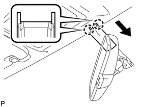
1. REMOVE INNER REAR VIEW MIRROR STAY HOLDER COVER
|
(a) Disengage the 2 claws and slide the inner rear view mirror stay holder cover as shown in the illustration. |
|
|
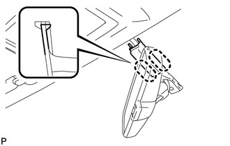
(b) Disengage the 2 claws and remove the inner rear view mirror stay holder cover. |
|
2. REMOVE INNER REAR VIEW MIRROR ASSEMBLY (w/o Automatic High Beam System)
|
(a) Disconnect the connector. |
|
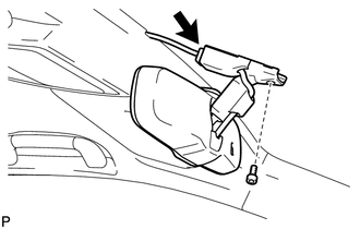
(b) Using a T20 "TORX" socket wrench, remove the screw and the inner rear view mirror assembly.
3. REMOVE INNER REAR VIEW MIRROR ASSEMBLY (w/ Automatic High Beam System)
NOTICE:
- Do not touch of the camera lens (built into the inner rear view mirror assembly) with a bare hand.
- Do not allow anything to adhere to the camera lens (built into the inner rear view mirror assembly).
- Do not apply strong impact to the inner rear view mirror assembly.
- Do not allow any liquids to get on the inner rear view mirror assembly.
|
(a) Disconnect the connector. |
|
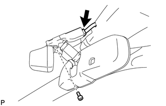
(b) Using a T20 "TORX" socket wrench, remove the screw and the inner rear view mirror assembly.
 Inspection
INSPECTION
PROCEDURE
1. INSPECT INNER REAR VIEW MIRROR ASSEMBLY
(a) Inspect operation of the electrochromic inner mirror.
(1) Connect a positive (+) lead from the battery to terminal 1 and a neg ...
 Installation
INSTALLATION
PROCEDURE
1. INSTALL INNER REAR VIEW MIRROR ASSEMBLY (w/o Automatic High Beam System)
(a) Using a T20 "TORX" socket wrench, install the inner rear view mirror assembly
with ...
Other materials about Toyota Venza:
Replacement
REPLACEMENT
PROCEDURE
1. RECOVER REFRIGERANT FROM REFRIGERATION SYSTEM
(a) Start up the engine.
(b) Turn the A/C switch on.
(c) Operate the cooler compressor at an engine speed of approximately 1000 rpm
for 5 to 6 minutes to circulate the refrigerant. T ...
Inspection
INSPECTION
PROCEDURE
1. INSPECT TRANSMISSION OIL CLEANER MAGNET
(a) Use the removed transmission oil cleaner magnets to collect any steel
chips. Examine the chips and particles in the automatic transaxle oil pan
sub-assembly and on the tr ...
Rear Power Window LH does not Operate with Rear Power Window Switch LH
DESCRIPTION
When the engine is running or the ignition switch is ON, the power window regulator
motor assembly (for rear LH side) is operated by the power window regulator switch
assembly (for rear LH side). The power window regulator motor has motor, reg ...

0.1547