Toyota Venza: On-vehicle Inspection
ON-VEHICLE INSPECTION
PROCEDURE
1. INSPECT DISCHARGE HEADLIGHT BULB
NOTICE:
Confirm the following items before replacing a discharge headlight bulb. If a malfunction is discovered and repaired, perform the inspection again to confirm the repair.
- Make sure that the high voltage socket of the light control ECU and discharge headlight bulb are connected normally.
- Make sure that there is no damage to the high voltage socket of the light control ECU or discharge headlight bulb connector.
HINT:
Even if a bulb seems to turn on normally, it may not be normal. Perform all the following steps in order because an abnormal condition might otherwise not be easy to duplicate.
(a) Prepare the vehicle:
Before performing the following inspection procedure, turn off the discharge headlight bulbs for more than 10 minutes to allow them to cool down sufficiently.
HINT:
Since it is necessary to find the cause of a malfunction that causes a discharge headlight bulb not to turn on, the discharge headlight bulbs should be inspected starting from a cooled off state.
(1) Turn on the discharge headlights for more than 25 minutes, and check that the bulbs illuminate normally when they are turned on.
HINT:
- Leave the headlights on for more than 25 minutes to stabilize the discharge headlight bulb arc tube voltage.
- A discharge headlight bulb that has almost reached the end of its life may turn off due to a headlight control ECU fail-safe function because the arc tube voltage is high.
(2) Repeatedly turn the discharge headlights off for 15 seconds and on for 15 seconds (5 times for each). Check that the bulbs illuminate normally.
HINT:
This inspection confirms the ability of the bulbs to start when hot.
(3) Turn off the discharge headlights for 3 minutes, and then turn on the discharge headlights for 3 minutes. Check that the bulbs illuminate normally when they are turned on.
HINT:
- A characteristic of discharge headlight bulbs is that their starting voltage is highest when 3 minutes have elapsed after being turned off. This is the most difficult situation for discharge bulbs to start in.
- This inspection is further confirmation of the ability of the bulbs to start when hot.
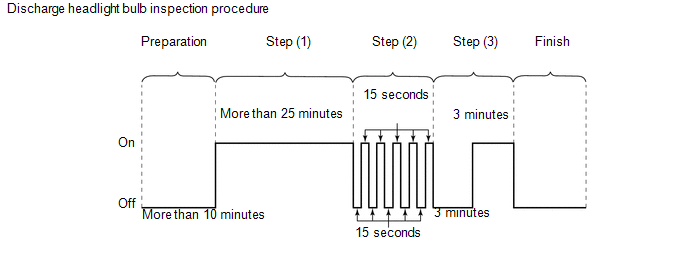
Standard:
The discharge headlight bulbs illuminate normally in all steps.
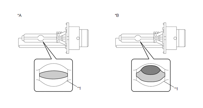
(4) Remove the discharge headlight bulb and perform a visual inspection of the arc tube.
Standard:
The inside of the arc tube is not bulging or deformed and is not clouded. However, a dull brown coloration inside the arc tube is normal.
 Text in Illustration
|
*A |
Discharge Headlight Bulb is Normal |
*B |
Discharge Headlight Bulb at End of Usable Life |
|
*1 |
Arc Tube |
- |
- |
 |
Inside of Arc Tube |
.png) |
Distortion / Clouded Area |
 Components
COMPONENTS
ILLUSTRATION
ILLUSTRATION
...
 Installation
INSTALLATION
PROCEDURE
1. INSTALL DISCHARGE HEADLIGHT BULB
HINT:
Use the same procedure for the RH side and LH side (See page
).
2. INSTALL LIGHT CONTROL ECU (for LH Side)
(a) Turn ...
Other materials about Toyota Venza:
On-vehicle Inspection
ON-VEHICLE INSPECTION
PROCEDURE
1. CONNECT TECHSTREAM
(a) Connect the Techstream to the DLC3.
(b) Start the engine and run it at idle.
(c) Enter the following menus: Chassis / ABS/VSC/TRAC / Active Test.
HINT:
Refer to the Techstream operator's manu ...
Terminals Of Ecu
TERMINALS OF ECU
1. CHECK MAIN BODY ECU (DRIVER SIDE JUNCTION BLOCK ASSEMBLY)
(a) Disconnect the 2A and 2F main body ECU (driver side junction block assembly)
connectors.
(b) Measure the voltage and resistance according to the value(s) in the table
be ...
Installation
INSTALLATION
PROCEDURE
1. INSTALL TELEVISION CAMERA ASSEMBLY (w/ Rear View Monitor System)
2. INSTALL BACK DOOR OPENER SWITCH ASSEMBLY
3. INSTALL NO. 1 BACK DOOR EMBLEM
4. INSTALL NO. 2 BACK DOOR NAME PLATE
5. INSTALL BACK DOOR OUTSIDE GARNIS ...

0.1153