Toyota Venza: Installation
INSTALLATION
PROCEDURE
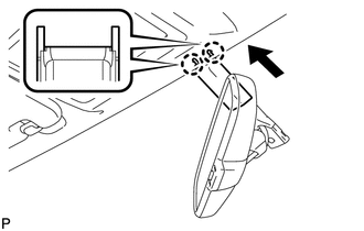
1. INSTALL INNER REAR VIEW MIRROR ASSEMBLY (w/o Automatic High Beam System)
(a) Using a T20 "TORX" socket wrench, install the inner rear view mirror assembly with the screw.
Torque:
1.5 N·m {15 kgf·cm, 13 in·lbf}
(b) Connect the connector.
2. INSTALL INNER REAR VIEW MIRROR ASSEMBLY (w/ Automatic High Beam System)
NOTICE:
- Do not touch the camera lens (built into the inner rear view mirror assembly) with a bare hand.
- Do not allow anything to adhere to the camera lens (built into the inner rear view mirror assembly).
- Do not apply strong impacts to the inner rear view mirror assembly.
- Do not allow any liquid to get on the inner rear view mirror assembly.
(a) Using a T20 "TORX" socket wrench, install the inner rear view mirror assembly with the screw.
Torque:
1.5 N·m {15 kgf·cm, 13 in·lbf}
(b) Connect the connector.
3. INSTALL INNER REAR VIEW MIRROR STAY HOLDER COVER
(a) Engage the 2 claws.
|
(b) Slide the inner rear view mirror stay holder cover and engage the 2 claws and install the cover as shown in the illustration. |
|
 Removal
REMOVAL
PROCEDURE
1. REMOVE INNER REAR VIEW MIRROR STAY HOLDER COVER
(a) Disengage the 2 claws and slide the inner rear view mirror stay holder
cover as shown in the illustration.
...

Other materials about Toyota Venza:
Front Blower Motor
Components
COMPONENTS
ILLUSTRATION
Installation
INSTALLATION
PROCEDURE
1. INSTALL FRONT BLOWER MOTOR SUB-ASSEMBLY
(a) Install the front blower motor sub-assembly with the 3 screws.
(b) Con ...
Reassembly
REASSEMBLY
PROCEDURE
1. INSTALL NO. 14 ROOF SILENCER PAD
(a) Align the markings on the roof headlining assembly with the No. 14 roof silencer
pad and install the silencer pad using hot-melt glue as shown in the illustration.
2. INSTALL NO. 1 ROOF WIRE ...
Operation Check
OPERATION CHECK
1. CHECK BASIC FUNCTIONS
(a) When the back door is partially closed, check that the motor operates to
fully close (lock) the back door.
(b) Check that the back door can be opened.
(c) When the back door is partially closed and then the mo ...

0.1392