Toyota Venza: Disassembly
DISASSEMBLY
PROCEDURE
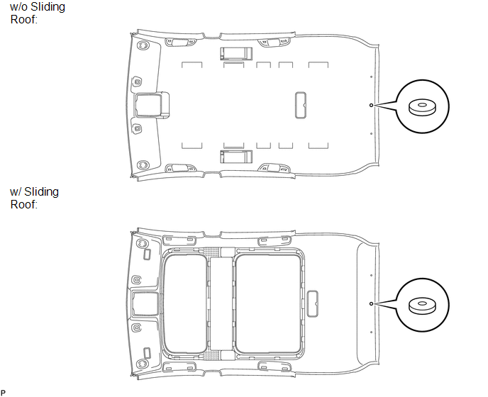
1. REMOVE NO. 2 ANTENNA CORD SUB-ASSEMBLY (w/o Sliding Roof)
.gif)
2. REMOVE NO. 2 ANTENNA CORD SUB-ASSEMBLY (w/ Sliding Roof)
3. REMOVE VANITY LIGHT ASSEMBLY
(a) Remove the vanity light assembly (See page
).
HINT:
Use the same procedure for the RH side and the LH side.
4. REMOVE FRONT SIDE RAIL SPACER LH (w/o Sliding Roof)
(a) Remove the front side rail spacer LH.
5. REMOVE FRONT SIDE RAIL SPACER RH (w/o Sliding Roof)
HINT:
Use the same procedure for the RH side and the LH side.
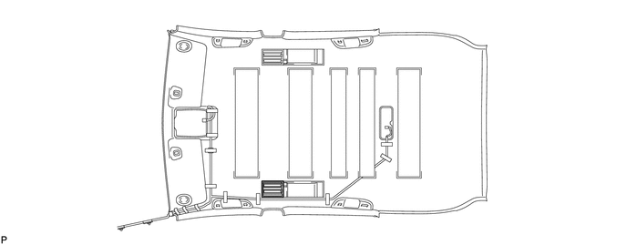
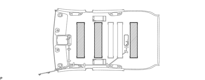
6. REMOVE NO. 3 ROOF SILENCER PAD (w/o Sliding Roof)
(a) Remove the 3 No. 3 roof silencer pads.
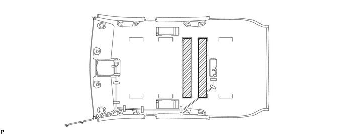
7. REMOVE NO. 2 ROOF SILENCER PAD (w/o Sliding Roof)
(a) Remove the 2 No. 2 roof silencer pads.
8. REMOVE NO. 1 ROOF WIRE (w/o Sliding Roof)
(a) Remove the adhesive tape.
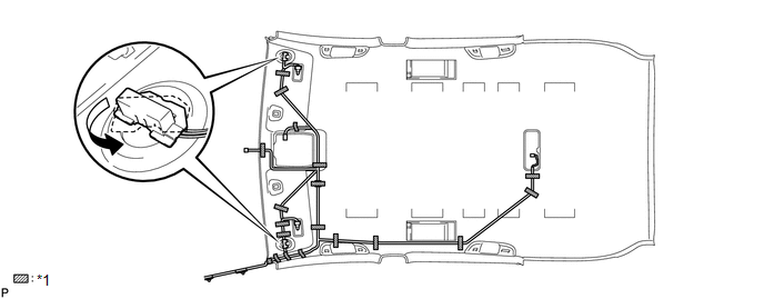 Text in Illustration
|
*1 |
Adhesive Tape |
- |
- |
(b) Turn the visor connectors counterclockwise approximately 90° and separate the connectors.
(c) Remove the No. 1 roof wire.
9. REMOVE NO. 1 ROOF WIRE (w/ Sliding Roof)
(a) Remove the adhesive tape.
(b) Turn the visor connectors counterclockwise approximately 90° and separate the connectors.
(c) Remove the No. 1 roof wire.
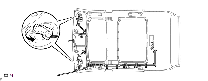 Text in Illustration
|
*1 |
Adhesive Tape |
- |
- |
10. REMOVE NO. 14 ROOF SILENCER PAD
(a) Remove the No. 14 roof silencer pad.
 Components
COMPONENTS
ILLUSTRATION
ILLUSTRATION
ILLUSTRATION
ILLUSTRATION
ILLUSTRATION
ILLUSTRATION
ILLUSTRATION
ILLUSTRATION
ILLUSTRATION
ILLUSTRATION
ILLUSTRATION
ILLUSTRATION ...
 Removal
REMOVAL
PROCEDURE
1. REMOVE FRONT DOOR SCUFF PLATE LH
(a) Disengage the 3 clips, 7 claws and guide, and remove the front door
scuff plate LH.
...
Other materials about Toyota Venza:
TS and CG Terminal Circuit
DESCRIPTION
In the Test Mode (signal check), a malfunction in the speed sensor that cannot
be detected when the vehicle is stopped can be detected while driving.
Transition to the sensor check mode can be performed by connecting terminals
TS and CG of th ...
Headlight Relay Circuit
DESCRIPTION
The main body ECU (driver side junction block assembly) controls the headlight
relays.
WIRING DIAGRAM
CAUTION / NOTICE / HINT
NOTICE:
Inspect the fuses for circuits related to this system before performing the following
inspection proc ...
Headlight Dimmer Switch
Components
COMPONENTS
ILLUSTRATION
Removal
REMOVAL
PROCEDURE
1. REMOVE SPIRAL CABLE WITH SENSOR SUB-ASSEMBLY
(See page )
2. REMOVE WINDSHIELD WIPER SWITCH ASSEMBLY
3. REMOVE HEADLIGHT DIMMER SWITCH ASSEMBLY
(a) Disconnect the con ...

0.1237