
Toyota Venza: Crankshaft Position Sensor
Components
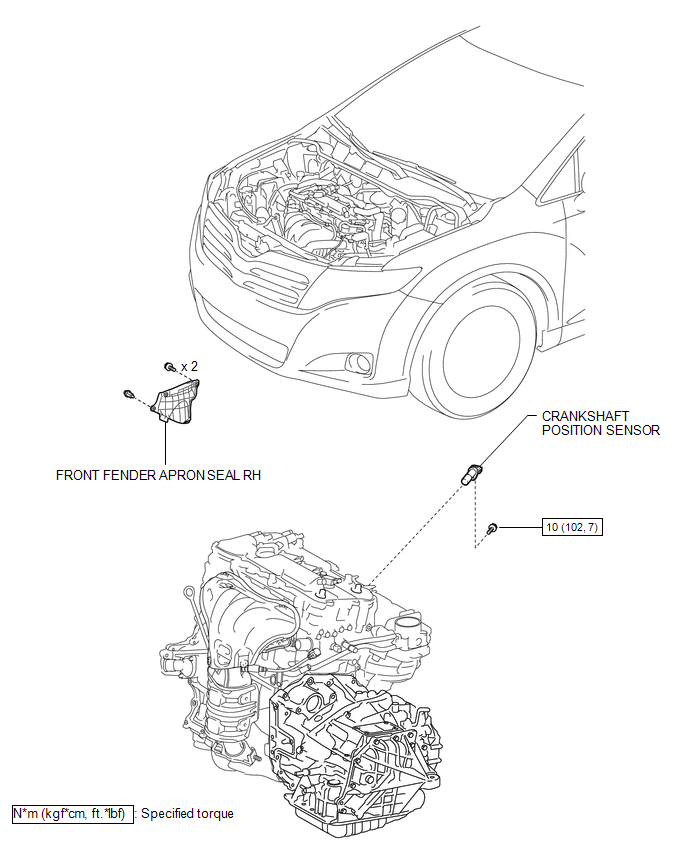
COMPONENTS
ILLUSTRATION
Removal
REMOVAL
PROCEDURE
1. REMOVE FRONT FENDER APRON SEAL RH
.gif)
2. REMOVE CRANKSHAFT POSITION SENSOR
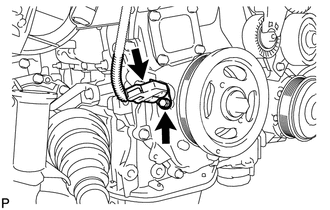
(a) Disconnect the sensor connector.
(b) Remove the bolt and sensor.
Inspection
INSPECTION
PROCEDURE
1. INSPECT CRANKSHAFT POSITION SENSOR
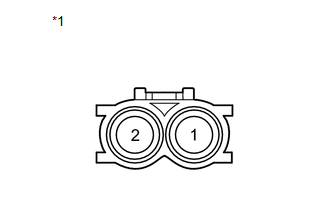 Text in Illustration
|
*1 |
Component without harness connected (Crank Position Sensor) |
(a) Measure the resistance according to the value(s) in the table below.
Standard Resistance:
|
Tester Connection |
Condition |
Specified Condition |
|---|---|---|
|
1 - 2 |
Cold |
1630 to 2740 Ω |
|
Hot |
2065 to 3225 Ω |
HINT:
In the table above, the terms "Cold" and "Hot" refer to the temperature of the coils. "Cold" means approximately -10 to 50°C (14 to 122°F). "Hot" means approximately 50 to 100°C (122 to 212°F).
If the result is not as specified, replace the crankshaft position sensor.
Installation
INSTALLATION
PROCEDURE
1. INSTALL CRANKSHAFT POSITION SENSOR
(a) Apply a light coat of engine oil to the O-ring of the crankshaft position sensor.
NOTICE:
If reusing the crankshaft position sensor, be sure to inspect the O-ring.
(b) Install the crankshaft position sensor to the timing chain cover sub-assembly with the bolt.
Torque:
10 N·m {102 kgf·cm, 7 ft·lbf}
NOTICE:
- If the crankshaft position sensor has been struck or dropped, replace it.
- Make sure that the O-ring is not cracked or moved out of place when installing the crankshaft position sensor.
(c) Connect the crankshaft position sensor connector.
2. INSPECT FOR OIL LEAK
3. INSTALL FRONT FENDER APRON SEAL RH
.gif)
 Camshaft Position Sensor
Components
COMPONENTS
ILLUSTRATION
Installation
INSTALLATION
PROCEDURE
1. INSTALL CAMSHAFT POSITION SENSOR (for Exhaust Side)
(a) Apply a light coat of engine oil to the O-ring of the cam ...
 Ecm
Ecm
...
Other materials about Toyota Venza:
Power Back Door cannot be Opened or Closed Using the Power Back Door Switch
DESCRIPTION
When the power back door cannot be opened or closed using the power back door
control switch, one of the following may be malfunctioning: 1) power back door control
switch circuit, 2) power back door ECU (power back door motor unit) or 3) main ...
Locking the driver’s doors from the outside without a key
Move the inside lock button to the
lock position.
Close the door.
►Vehicles with smart key system
The door cannot be locked if the “ENGINE START STOP” switch is in ACCESSORY or IGNITION
ON mode, or the electronic key is left inside the vehic ...
ECU Power Source Circuit
DESCRIPTION
This circuit provides power for main body ECU (driver side junction block assembly)
operation.
WIRING DIAGRAM
PROCEDURE
1.
CHECK DRIVER SIDE JUNCTION BLOCK ASSEMBLY (MAIN BODY ECU (POWER SOURCE))
...

0.1529