Toyota Venza: Removal
REMOVAL
CAUTION / NOTICE / HINT
HINT:
- The front side fix window assembly can be reused. When installing the window, if any of the clips on the quarter window glass are broken, butyl tape can be used to support the glass until the applied adhesive hardens.
- When using butyl tape to temporarily secure the window, make sure that the butyl tape is not applied exactly at the original clip location. If the butyl tape is applied exactly at the clip location, it will cause the window to protrude
- Use the same procedure for the RH side and LH side.
- The procedure listed below is for the LH side.
PROCEDURE
1. REMOVE REAR DOOR SCUFF PLATE
.gif)
2. DISCONNECT REAR DOOR OPENING TRIM WEATHERSTRIP
3. REMOVE TONNEAU COVER ASSEMBLY (w/ Tonneau Cover)
4. REMOVE DECK BOARD ASSEMBLY
5. REMOVE NO. 3 DECK BOARD SUB-ASSEMBLY
6. REMOVE DECK SIDE TRIM BOX LH
7. REMOVE NO. 2 DECK BOARD SUB-ASSEMBLY
8. REMOVE DECK SIDE TRIM BOX RH
9. REMOVE NO. 1 DECK BOARD
10. REMOVE REAR SEAT SUB FLOOR PANEL ASSEMBLY
11. REMOVE REAR FLOOR FINISH PLATE
12. REMOVE REAR SEAT HEADREST ASSEMBLY (for LH Side)
13. REMOVE REAR SEAT INNER TRACK BRACKET COVER (for LH Side)
14. REMOVE REAR SEAT OUTER TRACK BRACKET COVER (for LH Side)
15. DISCONNECT REAR SEAT NO. 2 RECLINING CONTROL CABLE SUB-ASSEMBLY (for LH Side)
16. REMOVE REAR SEAT ASSEMBLY LH (for LH Side)
17. REMOVE REAR SEAT HEADREST ASSEMBLY (for RH Side)
18. REMOVE REAR SEAT CENTER HEADREST ASSEMBLY (for RH Side)
19. REMOVE REAR SEAT INNER TRACK BRACKET COVER (for RH Side)
20. REMOVE REAR SEAT OUTER TRACK BRACKET COVER (for RH Side)
21. DISCONNECT REAR SEAT RECLINING CONTROL CABLE SUB-ASSEMBLY (for RH Side)
22. REMOVE REAR SEAT ASSEMBLY RH (for RH Side)
23. REMOVE RECLINING REMOTE CONTROL BEZEL
24. REMOVE LUGGAGE HOLD BELT STRIKER ASSEMBLY
25. DISCONNECT REAR SEAT OUTER BELT ASSEMBLY
26. REMOVE DECK TRIM SIDE PANEL ASSEMBLY LH (for LH Side)
27. REMOVE DECK TRIM SIDE PANEL ASSEMBLY RH (for RH Side)
28. REMOVE ROOF SIDE INNER GARNISH ASSEMBLY
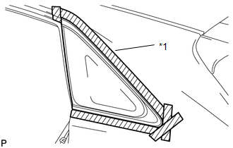
29. REMOVE QUARTER WINDOW ASSEMBLY
|
(a) Apply protective tape to the outer surface of the vehicle body to prevent scratches. Text in Illustration
|
|
|
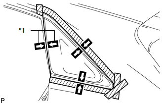
(b) Place matchmarks on the quarter window assembly and vehicle body on the locations indicated in the illustration. Text in Illustration
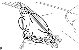
HINT: Do not allow the piano wire to interfere with the clips. |
|
|
(c) Pass a piano wire between the vehicle body and glass from the interior as shown in the illustration. HINT: Ensure not to interfere with the clips when passing the piano wire. Text in Illustration
|
|
(d) Tie both wire ends to wooden blocks or similar objects that can serve as handles.
NOTICE:
When separating the quarter window assembly from the vehicle, be careful not to damage the paint or interior and exterior ornaments.
(e) Cut off the adhesive by pulling the piano wire around the quarter window assembly.
NOTICE:
Leave as much adhesive on the vehicle body as possible when cutting through the adhesive.
|
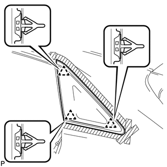
(f) Disengage the 3 clips. |
|
(g) Using suction cups, remove the glass.
NOTICE:
Be careful not to drop the glass.
30. CLEAN VEHICLE BODY
|
(a) Clean and shape the contact surfaces of the vehicle body. Text in Illustration
(1) Using a knife, cut away excess adhesive on the contact surfaces of the vehicle body as shown in the illustration. NOTICE: Be careful not to damage the vehicle body. HINT: Leave as much adhesive on the vehicle body as possible. |
|
.png)
(b) Clean the contact surfaces of the vehicle body with a piece of cloth saturated with cleaner.
HINT:
Even if all the adhesive has been removed, clean the vehicle body.
 Components
COMPONENTS
ILLUSTRATION
ILLUSTRATION
ILLUSTRATION
ILLUSTRATION
ILLUSTRATION
ILLUSTRATION
...
 Installation
INSTALLATION
PROCEDURE
1. CLEAN QUARTER WINDOW ASSEMBLY
(a) Clean the outer edges of the quarter window assembly with a non-residue
solvent.
NOTICE:
Do not touch t ...
Other materials about Toyota Venza:
System Description
SYSTEM DESCRIPTION
1. TOUCH SWITCH OUTLINE
(a) Touch switches are touch-sensitive (interactive) switches operated by touching
the screen. When a switch is pressed, the outer film bends in to contact the inner
glass at the pressed position. By doing this, ...
Reassembly
REASSEMBLY
PROCEDURE
1. INSTALL NO. 1 CENTER SUPPORT BEARING ASSEMBLY
(a) Set the No. 1 center support bearing on the intermediate shaft as
shown in the illustration.
NOTICE:
Make sure to install the bearing in the correct position.
...
Problem Symptoms Table
PROBLEM SYMPTOMS TABLE
HINT:
Use the table below to help determine the cause of problem symptoms.
If multiple suspected areas are listed, the potential causes of the symptoms
are listed in order of probability in the "Suspected Area" ...

0.1308