Toyota Venza: Components
COMPONENTS
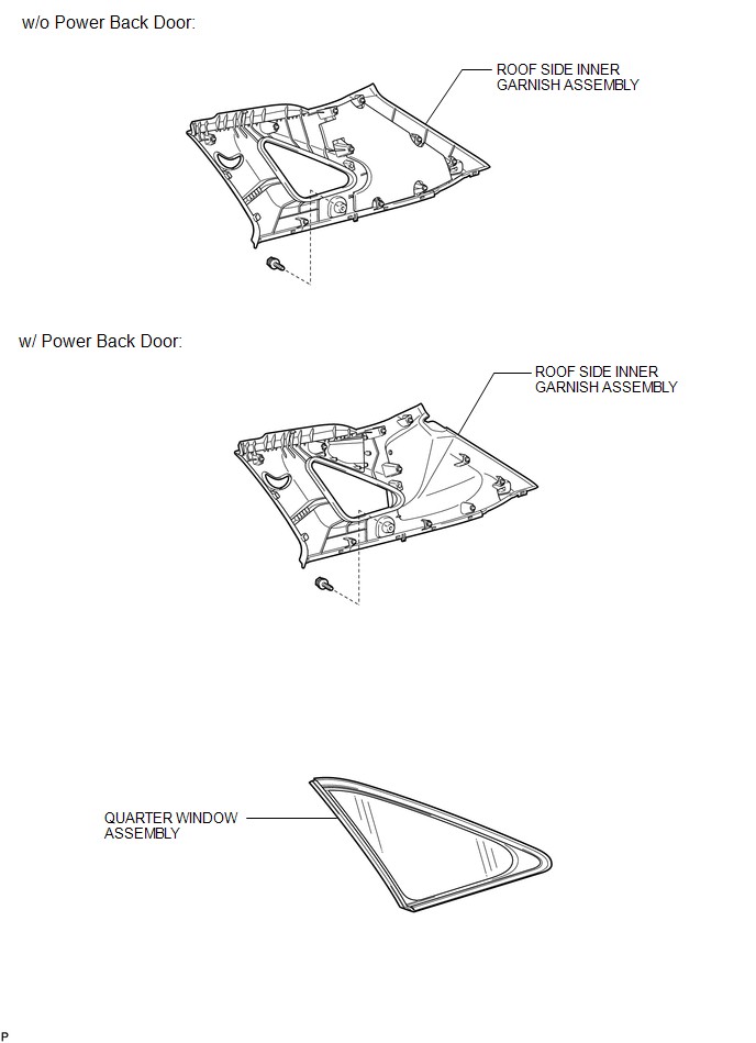
ILLUSTRATION
.png)
ILLUSTRATION
.png)
ILLUSTRATION
.png)
ILLUSTRATION
.png)
ILLUSTRATION
.png)
ILLUSTRATION

 Removal
REMOVAL
CAUTION / NOTICE / HINT
HINT:
The front side fix window assembly can be reused. When installing the
window, if any of the clips on the quarter window glass are broken, butyl
...
Other materials about Toyota Venza:
Removal
REMOVAL
CAUTION / NOTICE / HINT
NOTICE:
If automatic transaxle assembly parts are replaced, refer to Parts Replacement
Compensation Table to determine if any additional operations are necessary (See
page ).
PROCEDURE
1. REMOVE ENGINE ASSEMBLY WITH TR ...
Terminals Of Ecu
TERMINALS OF ECU
1. CHECK AIR CONDITIONING AMPLIFIER ASSEMBLY
(a) Disconnect the D47 air conditioning amplifier assembly connector.
(b) Measure the voltage and resistance according to the value(s) in the table
below.
HINT:
Measure the values on the wi ...
Knock Sensor 1 Circuit Low Input (Bank 1 or Single Sensor) (P0327,P0328)
DESCRIPTION
Flat-type knock sensors (non-resonant type) have structures that can detect vibrations
between approximately 5 and 15 kHz.
Knock sensors are fitted onto the engine block to detect engine knocking.
The knock sensor contains a piezoelectric elem ...

0.1278