Toyota Venza: Inspection
INSPECTION
PROCEDURE
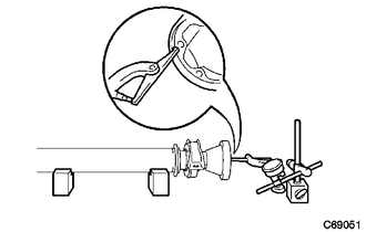
1. INSPECT UNIVERSAL JOINT SPIDER ASSEMBLY
|
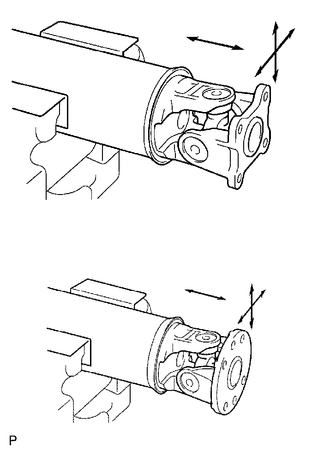
(a) Check the spider bearing axial play by turning the flange while holding the shaft tightly. HINT: If necessary, replace the propeller with center bearing shaft assembly. |
|
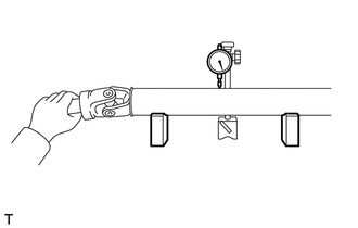
2. INSPECT INTERMEDIATE SHAFT
|
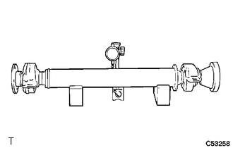
(a) Using a dial indicator, inspect the intermediate shaft sub-assembly. Maximum runout: 0.4 mm (0.0157 in.) NOTICE: The dial indicator must be set at a right angle to the center of the intermediate shaft. If the shaft runout is greater than the maximum, replace the propeller with center bearing shaft assembly. |
|
|
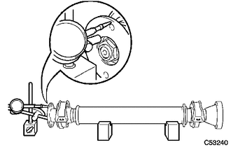
(b) Using a dial indicator, inspect the front side universal joint flange runout in the vertical direction. Maximum runout: 0.1 mm (0.00394 in.) If the flange runout is greater than the maximum, replace the propeller with center bearing shaft assembly. |
|
|
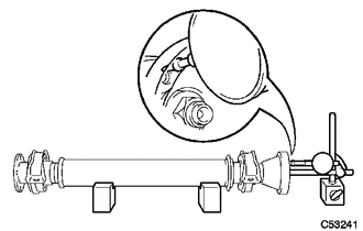
(c) Using a dial indicator, inspect the rear side universal joint flange runout in the vertical direction. Maximum runout: 0.1 mm (0.00394 in.) If the flange runout is greater than the maximum, replace the propeller with center bearing shaft assembly. |
|
|
(d) Using a dial indicator, inspect the rear side universal joint flange runout in the horizontal direction. Maximum runout: 0.1 mm (0.00394 in.) If the flange runout is greater than the maximum, replace the propeller with center bearing shaft assembly. |
|
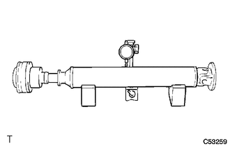
3. INSPECT PROPELLER SHAFT
|
(a) Using a dial indicator, inspect the propeller shaft. Maximum runout: 0.4 mm (0.0157 in.) NOTICE: The dial indicator must be set at a right angle to the center of the propeller shaft. If the shaft runout is greater than the maximum, replace the propeller with center bearing shaft assembly. |
|
4. INSPECT REAR PROPELLER SHAFT
|
(a) Using a dial indicator, inspect the rear propeller shaft. Maximum runout: 0.4 mm (0.0157 in.) NOTICE: The dial indicator must be set at a right angle to the center of the rear propeller shaft. If the shaft runout is greater than the maximum, replace the propeller with center bearing shaft assembly. |
|
5. INSPECT NO. 1 CENTER SUPPORT BEARING ASSEMBLY
|
(a) Turn the No. 1 center support bearing assembly by hand while applying force in the rotation direction. Check that the bearing turns smoothly. |
|
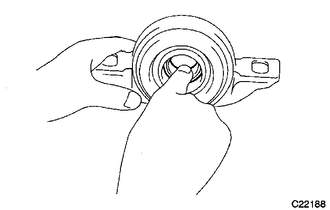
(b) Check that the seals and bracket are not cracked or damaged.
If the No. 1 center support bearing assembly is damaged, worn, or does not turn freely, replace it.
6. INSPECT NO. 2 CENTER SUPPORT BEARING ASSEMBLY
(a) Turn the No. 2 center support bearing assembly by hand while applying force in the rotation direction. Check that the bearing turns smoothly.
(b) Check that the seals and bracket are not cracked or damaged.
If the No. 2 center support bearing assembly is damaged, worn, or does not turn freely, replace it.
 Disassembly
DISASSEMBLY
PROCEDURE
1. REMOVE PROPELLER SHAFT
(a) Place matchmarks on both flanges.
Text in Illustration
*1
Matchmark
...
 Installation
INSTALLATION
PROCEDURE
1. TEMPORARILY TIGHTEN PROPELLER WITH CENTER BEARING SHAFT ASSEMBLY
(a) Remove SST from the transfer.
SST: 09325-20010
...
Other materials about Toyota Venza:
Disposal
DISPOSAL
CAUTION / NOTICE / HINT
CAUTION:
Before performing pre-disposal deployment of any SRS part, review and closely
follow all applicable environmental and hazardous material regulations. Pre-disposal
deployment may be considered hazardous material ...
Reassembly
REASSEMBLY
PROCEDURE
1. INSTALL REAR CONSOLE ARMREST ASSEMBLY
(a) Temporarily install the rear console armrest assembly.
(b) Push in the box door hinge shafts by hand as far as possible.
HINT:
The illustration is for the LH sid ...
Inspection
INSPECTION
PROCEDURE
1. INSPECT COMPRESSOR AND MAGNETIC CLUTCH (A/C LOCK SENSOR)
(a) Measure the resistance according to the value(s) in the table below.
Standard Resistance:
Tester Connection
Condition
...

0.1706